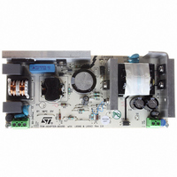
EVL6566A-75WADP STMicroelectronics, EVL6566A-75WADP Datasheet - Page 16

EVL6566A-75WADP
Manufacturer Part Number
EVL6566A-75WADP
Description
BOARD EVAL FOR L6566A
Manufacturer
STMicroelectronics
Type
Power Factor Correctionr
Datasheets
1.L6566ATR.pdf
(51 pages)
2.TSM1014IDT.pdf
(10 pages)
3.L6563ATR.pdf
(39 pages)
4.EVL6566A-75WADP.pdf
(8 pages)
Specifications of EVL6566A-75WADP
Main Purpose
AC/DC, Primary and Secondary Side with PFC
Outputs And Type
1, Isolated
Power - Output
75W
Voltage - Output
19V
Current - Output
4A
Voltage - Input
90 ~ 264VAC
Frequency - Switching
65kHz
Board Type
Fully Populated
Utilized Ic / Part
L6563, L6566A, TSM1014
Input Voltage
90 V to 264 V
Output Voltage
19 V
Dimensions
78 mm x 174 mm
Product
Power Management Modules
Lead Free Status / RoHS Status
Lead free / RoHS Compliant
Regulator Topology
-
Lead Free Status / Rohs Status
Lead free / RoHS Compliant
For Use With/related Products
L6563, L6566A
Other names
497-6449
Available stocks
Company
Part Number
Manufacturer
Quantity
Price
Application information
6
6.1
16/39
Application information
Overvoltage protection
Normally, the voltage control loop keeps the output voltage V
close to its nominal value, set by the ratio of the resistors R1 and R2 of the output divider.
Neglecting the ripple components, under steady state conditions the current through R1
equals that through R2. Considering that the non-inverting input of the error amplifier is
internally biased at 2.5V, the voltage at pin INV will be 2.5V as well, then:
Equation 1
If the output voltage experiences an abrupt change ∆Vo the voltage at pin INV is kept at 2.5V
by the local feedback of the error amplifier, a network connected between pins INV and
COMP that introduces a long time constant. Then the current through R2 remains equal to
2.5/R2 but that through R1 becomes:
Equation 2
The difference current ∆I
and enter the error amplifier (pin COMP). This current is monitored inside the IC and when it
reaches about 18 µA the output voltage of the multiplier is forced to decrease, thus reducing
the energy drawn from the mains. If the current exceeds 20 µA, the OVP is triggered
(Dynamic OVP), and the external power transistor is switched off until the current falls
approximately below 5 µA. However, if the overvoltage persists (e.g. in case the load is
completely disconnected), the error amplifier will eventually saturate low hence triggering an
internal comparator (Static OVP) that will keep the external power switch turned off until the
output voltage comes back close to the regulated value. The output overvoltage that is able
to trigger the OVP function is then:
Equation 3
R1
= I’
R1
I
- I’
R2
R1
I'
=
R1
∆V
= ∆V
I
R1
O
=
= R1 · 20 · 10
V
--------------------------------------- -
=
O
O
/R1 will flow through the compensation network
2.5
------- -
R2
–
2.5
R1
=
+
V
--------------------- -
∆
O
V
-6
R1
–
O
2.5
O
of the PFC pre-regulator
L6563 - L6563A


