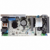
EVL6566A-75WADP STMicroelectronics, EVL6566A-75WADP Datasheet - Page 27

EVL6566A-75WADP
Manufacturer Part Number
EVL6566A-75WADP
Description
BOARD EVAL FOR L6566A
Manufacturer
STMicroelectronics
Type
Power Factor Correctionr
Datasheets
1.L6566ATR.pdf
(51 pages)
2.TSM1014IDT.pdf
(10 pages)
3.L6563ATR.pdf
(39 pages)
4.EVL6566A-75WADP.pdf
(8 pages)
Specifications of EVL6566A-75WADP
Main Purpose
AC/DC, Primary and Secondary Side with PFC
Outputs And Type
1, Isolated
Power - Output
75W
Voltage - Output
19V
Current - Output
4A
Voltage - Input
90 ~ 264VAC
Frequency - Switching
65kHz
Board Type
Fully Populated
Utilized Ic / Part
L6563, L6566A, TSM1014
Input Voltage
90 V to 264 V
Output Voltage
19 V
Dimensions
78 mm x 174 mm
Product
Power Management Modules
Lead Free Status / RoHS Status
Lead free / RoHS Compliant
Regulator Topology
-
Lead Free Status / Rohs Status
Lead free / RoHS Compliant
For Use With/related Products
L6563, L6566A
Other names
497-6449
Available stocks
Company
Part Number
Manufacturer
Quantity
Price
L6563 - L6563A
6.6
Figure 40. 80W, wide-range-mains PFC pre-regulator with tracking boost function active
Figure 41. Tracking boost and voltage feedforward blocks
(88V to 264V)
Vac
4A/250V
FUSE
Inductor saturation detection (L6563 only)
Boost inductor's hard saturation may be a fatal event for a PFC pre-regulator: the current
upslope becomes so large (50-100 times steeper, see
sense propagation delay the current may reach abnormally high values. The voltage drop
caused by this abnormal current on the sense resistor reduces the gate-to-source voltage,
so that the MOSFET may work in the active region and dissipate a huge amount of power,
which leads to a catastrophic failure after few switching cycles.
However, in some applications such as ac-dc adapters, where the PFC pre-regulator is
turned off at light load for energy saving reasons, even a well-designed boost inductor may
occasionally slightly saturate when the PFC stage is restarted because of a larger load
demand. This happens when the restart occurs at an unfavorable line voltage phase, so that
the output voltage may drop significantly below the rectified peak voltage. As a result, in the
+
-
Vout
4 x 1N4007
BRIDGE
I
I
R1
R2
R1
R2
51.1 k Ω
INV
0.22 µF
400V
R2
C1
1
3.3 M Ω
3.3 M Ω
9.5V
R1a
R1b
I
TBO
2.2nF
C2
2.5V
Supply Voltage
10.3 to 22V
22 m F
25V
C3
+
-
1:1 CURRENT
E/A
L6563A
MIRROR
L6563
COMP
470 nF
C4
14
3
12
8
I
TBO
T
5
68 k Ω
2
9
R3
10
390 k Ω
11
L6563
R10
MULTIPLIER
6
R
TBO
T
6
2
21 k Ω
reference
R4
current
3V
62 k Ω
C6 100 nF
R5
7
1
13
4
10 nF
1/V
C
C7
+
1 µF
-
VFF
C5
FF
Figure
2
10 Ω
R6
0.68 Ω
R7a,b
1/4 W
5
"ideal"
diode
9.5V
42) that during the current
STTH1L06
R
STP8NM50
3
FF
D1
MOS
Application information
MULT
Rectified mains
R5
R6
47.5 k Ω
1 M Ω
1 M Ω
NTC
R8a
R8b
R9
34.8 k Ω
3.3 M Ω
3.3 M Ω
R10a
R10b
R11
Vo=200 to 385 V
Po=80W
27/39
56 µF
400V
C6


