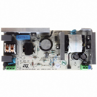
EVL6566A-75WADP STMicroelectronics, EVL6566A-75WADP Datasheet - Page 29

EVL6566A-75WADP
Manufacturer Part Number
EVL6566A-75WADP
Description
BOARD EVAL FOR L6566A
Manufacturer
STMicroelectronics
Type
Power Factor Correctionr
Datasheets
1.L6566ATR.pdf
(51 pages)
2.TSM1014IDT.pdf
(10 pages)
3.L6563ATR.pdf
(39 pages)
4.EVL6566A-75WADP.pdf
(8 pages)
Specifications of EVL6566A-75WADP
Main Purpose
AC/DC, Primary and Secondary Side with PFC
Outputs And Type
1, Isolated
Power - Output
75W
Voltage - Output
19V
Current - Output
4A
Voltage - Input
90 ~ 264VAC
Frequency - Switching
65kHz
Board Type
Fully Populated
Utilized Ic / Part
L6563, L6566A, TSM1014
Input Voltage
90 V to 264 V
Output Voltage
19 V
Dimensions
78 mm x 174 mm
Product
Power Management Modules
Lead Free Status / RoHS Status
Lead free / RoHS Compliant
Regulator Topology
-
Lead Free Status / Rohs Status
Lead free / RoHS Compliant
For Use With/related Products
L6563, L6566A
Other names
497-6449
Available stocks
Company
Part Number
Manufacturer
Quantity
Price
L6563 - L6563A
Figure 43. Interface circuits that let DC-DC converter’s controller IC disable the L6563/A at light
L5991/A
L6668
Vcc
16
100 nF
load
16
The third communication line is the PWM_STOP pin (pin 9), which works in conjunction with
the RUN pin (pin 10). The purpose of the PWM_STOP pin is to inhibit the PWM activity of
both the PFC stage and the cascaded DC-DC converter. The pin is an open collector,
normally open, that goes low if the device is disabled by a voltage lower than 0.52V on the
RUN pin. It is important to point out that this function works correctly in systems where the
PFC stage is the master and the cascaded DC-DC converter is the slave or, in other words,
where the PFC stage starts first, powers both controllers and enables/disables the operation
of the DC-DC stage.
This function is quite flexible and can be used in different ways. In systems comprising an
auxiliary converter and a main converter (e.g. desktop PC's silver box or hi-end LCD-TV),
where the auxiliary converter also powers the controllers of the main converter, the pin RUN
can be used to start and stop the main converter. In the simplest case, to enable/disable the
PWM controller the PWM_STOP pin can be connected to either the output of the error
amplifier
use of the soft-start pin allows the designer to delay the start-up of the DC-DC stage with
respect to that of the PFC stage, which is often desired. An underlying assumption in order
for that to work properly is that the UVLO thresholds of the PWM controller are certainly
higher than those of the L6563/A.
4
14
ST-BY
Vref
PFC_STOP
100
k Ω
(Figure 44
10 k
k Ω
150
k Ω
150
k Ω
27
Ω
BC557
BC557
2.2 k
8.2 V
Ω
L6599
a) or, if the chip is provided with it, to its soft-start pin
BC547
k Ω
47
L6563
7
BC547
PFC_OK
Vcc
14
L6563A
L6563
14
PFC_STOP
PFC_OK
L5991/A
(RUN)
VREF
8
L6668
7
(10)
100 nF
16
4
100 k
ST-BY
Vref
L6563A
L6563
14 PFC_STOP
100
k Ω
Ω
k Ω
150
150
k Ω
k Ω
27
2.2 k
Ω
BC557
Application information
Vcc
PFC_OK
(RUN)
BC547
100 nF
14
L6563
(Figure 44
BC557
7
(10)
BC547
L6563A
k Ω
L6563
15
Supply_Bus
b). The
29/39


