AG920-07E NVE, AG920-07E Datasheet - Page 109
AG920-07E
Manufacturer Part Number
AG920-07E
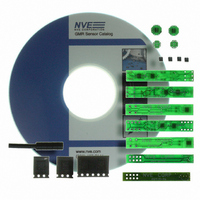
Description
KIT EVALUATION GT SENSOR
Manufacturer
NVE
Specifications of AG920-07E
Sensor Type
Magnetic. GMR (Giant Magnetoresistive)
Interface
Analog
Embedded
No
Utilized Ic / Part
ABL & AKL Series GT Sensors
Lead Free Status / RoHS Status
Lead free / RoHS Compliant
Voltage - Supply
-
Sensitivity
-
Sensing Range
-
Other names
391-1063


Application Notes for GT Sensors
General Theory of Operation of Differential Sensors (Gradiometers)
Differential sensors, or gradiometers, provide an output signal by sensing the gradient of the magnetic
field across the sensor IC. For example, a typical GMR sensor of this type will have four resistive
sensor elements on the IC, two on the left side of the IC, and two on the right. These resistive sensor
elements will be wired together in a Wheatstone bridge configuration. When a magnetic field
approaches the sensor IC from the right, the right two resistive sensor elements will decrease in
resistance before the elements on the left. This leads to an imbalance condition in the bridge, providing
a signal output from the bridge terminals.
Note that if a uniform magnetic field is applied to the sensor IC, all the resistive sensor elements will
change at the same time and the same amount, thus leading to no signal output from the bridge
terminals. Therefore, a differential sensor cannot be used as a magnetometer or an absolute field
detector; it must be used to detect the presence of a magnetic gradient field.
Gradient fields are present at the edge of magnetic encoders and magnetically biased gear teeth. As a
result, differential sensor elements are ideally suited for speed and position detection in these
applications.
GT Sensor Operation with Permanent Magnet Bias
Magnetic encoders generate their own magnetic field, but a gear tooth wheel does not, so if a
differential sensor is to be used to detect gear teeth, a permanent magnet is required to generate a
magnetic bias field. The differential magnetic sensor will then be used to detect variations in the field
of the permanent magnet as the gear tooth passes by in close proximity.
R3
R4
Field Decreases as Distance from Source Increases
www.nve.com
R1 and R2 see a Larger Field than R3 and R4
GT Sensor
phone: 952-829-9217 fax: 952-829-9189
- 109 -
R1
R2
Application Notes
Out-
Magnetic
R4
R2
Source
Point
Field
of
R1
R3
Out+
Related parts for AG920-07E
Image
Part Number
Description
Manufacturer
Datasheet
Request
R

Part Number:
Description:
KIT EVALUATION GT SENSOR
Manufacturer:
NVE
Datasheet:

Part Number:
Description:
ISOLATOR HS MAG DIGITAL 8SOIC
Manufacturer:
NVE
Datasheet:
Part Number:
Description:
ISOLATOR HS DIGITAL 125C 8SOIC
Manufacturer:
NVE
Datasheet:

Part Number:
Description:
HI-SPD 4CHANN COUPLER 16-SOIC LF
Manufacturer:
NVE
Datasheet:
Part Number:
Description:
ISOLATOR HS MAG DIGITAL 16SOIC
Manufacturer:
NVE
Datasheet:
Part Number:
Description:
ISOLATOR HS MAG DIGITAL 8SOIC
Manufacturer:
NVE
Datasheet:
Part Number:
Description:
IC DIFFER BUS TRANSC 16 SOIC
Manufacturer:
NVE
Datasheet:
Part Number:
Description:
ISOLATOR HS MAG DIGITAL 16SOICW
Manufacturer:
NVE
Datasheet:

Part Number:
Description:
ISOLATOR RS422/485 INTFC 16SOICW
Manufacturer:
NVE
Datasheet:
Part Number:
Description:
ISOLATOR HS MAG DIGITAL 16SOICW
Manufacturer:
NVE
Datasheet:

Part Number:
Description:
IC, DIGITAL ISOLATOR, 12NS, NSOIC-8
Manufacturer:
NVE
Datasheet:

Part Number:
Description:
IC, DIGITAL ISOLATOR, 12NS, DIP-8
Manufacturer:
NVE
Datasheet:
Part Number:
Description:
IC TXRX ISOLATED CAN HS 16SOIC
Manufacturer:
NVE
Datasheet: