AG920-07E NVE, AG920-07E Datasheet - Page 83
AG920-07E
Manufacturer Part Number
AG920-07E
Description
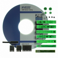
KIT EVALUATION GT SENSOR
Manufacturer
NVE
Specifications of AG920-07E
Sensor Type
Magnetic. GMR (Giant Magnetoresistive)
Interface
Analog
Embedded
No
Utilized Ic / Part
ABL & AKL Series GT Sensors
Lead Free Status / RoHS Status
Lead free / RoHS Compliant
Voltage - Supply
-
Sensitivity
-
Sensing Range
-
Other names
391-1063


Application Notes
This change in resistance is the GMR effect.
The size of the resistance decrease is typically 4% to over 20%, depending on the material structure of
the GMR films. Most of NVE’s sensor products rely on a GMR material which exhibits 14% to 16%
decrease in resistance. The “percent GMR” of a given material is calculated using the following
formula:
% GMR = Change in Resistance / Minimum Resistance
For example, assume an electrical resistor is implemented with GMR material, and it shows a nominal
resistance of 5000 Ohms. Then a magnetic field is applied and with this field a minimum resistance of
4400 Ohms is achieved. The percent GMR is then 600/4400, or about 13.6%.
Not all GMR materials operate in the manner described above. All GMR materials rely on modulating
the difference between the magnetization directions of adjacent layers in the GMR film structure, but
some achieve this modulation in different ways. The other most common type of GMR material is
referred to as a “spin valve” GMR material. This type of material does not necessarily rely on anti-
ferromagnetic coupling of the adjacent magnetic layers in the GMR film. In this case one of the
magnetic layers is “pinned,” or fixed with respect to its magnetization direction. The magnetization
direction of the pinned layer will not move when exposed to normal operating magnetic fields.
Therefore, the externally applied magnetic field will modulate the direction of the other magnetic
layer, referred to as the “free” layer. As the angle between the free layer and the pinned layer varies,
the mean free path length of the electrons in the GMR film also varies, and therefore the electrical
resistance will change.
Fixing the magnetization direction of the pinned layer in spin valve GMR materials can be done in a
variety of ways. However, it is important that the layer is pinned in a robust manner; otherwise, the
pinning can be undone by application of a large magnetic field. This will destroy the operation of the
sensor. NVE uses the application of large magnetic fields and high anneal temperatures (over 240°C)
to set the pinned layer of the film. This layer cannot be unpinned with the application of any magnetic
field in the normal temperature range of operation. Therefore, the sensor cannot be damaged by large
magnetic fields. This is also true of NVE’s other GMR sensors; no damage to any NVE GMR sensor
product can result due to the application of extremely large magnetic fields.
One of NVE’s competitors in Europe introduced a GMR sensor in 1997 that could be damaged by
magnetic fields in the 250 Gauss range. This product has since been discontinued.
- 83 -
www.nve.com
phone: 952-829-9217 fax: 952-829-9189
Related parts for AG920-07E
Image
Part Number
Description
Manufacturer
Datasheet
Request
R

Part Number:
Description:
KIT EVALUATION GT SENSOR
Manufacturer:
NVE
Datasheet:

Part Number:
Description:
ISOLATOR HS MAG DIGITAL 8SOIC
Manufacturer:
NVE
Datasheet:
Part Number:
Description:
ISOLATOR HS DIGITAL 125C 8SOIC
Manufacturer:
NVE
Datasheet:

Part Number:
Description:
HI-SPD 4CHANN COUPLER 16-SOIC LF
Manufacturer:
NVE
Datasheet:
Part Number:
Description:
ISOLATOR HS MAG DIGITAL 16SOIC
Manufacturer:
NVE
Datasheet:
Part Number:
Description:
ISOLATOR HS MAG DIGITAL 8SOIC
Manufacturer:
NVE
Datasheet:
Part Number:
Description:
IC DIFFER BUS TRANSC 16 SOIC
Manufacturer:
NVE
Datasheet:
Part Number:
Description:
ISOLATOR HS MAG DIGITAL 16SOICW
Manufacturer:
NVE
Datasheet:

Part Number:
Description:
ISOLATOR RS422/485 INTFC 16SOICW
Manufacturer:
NVE
Datasheet:
Part Number:
Description:
ISOLATOR HS MAG DIGITAL 16SOICW
Manufacturer:
NVE
Datasheet:

Part Number:
Description:
IC, DIGITAL ISOLATOR, 12NS, NSOIC-8
Manufacturer:
NVE
Datasheet:

Part Number:
Description:
IC, DIGITAL ISOLATOR, 12NS, DIP-8
Manufacturer:
NVE
Datasheet:
Part Number:
Description:
IC TXRX ISOLATED CAN HS 16SOIC
Manufacturer:
NVE
Datasheet: