AG920-07E NVE, AG920-07E Datasheet - Page 123
AG920-07E
Manufacturer Part Number
AG920-07E
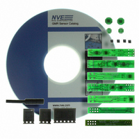
Description
KIT EVALUATION GT SENSOR
Manufacturer
NVE
Specifications of AG920-07E
Sensor Type
Magnetic. GMR (Giant Magnetoresistive)
Interface
Analog
Embedded
No
Utilized Ic / Part
ABL & AKL Series GT Sensors
Lead Free Status / RoHS Status
Lead free / RoHS Compliant
Voltage - Supply
-
Sensitivity
-
Sensing Range
-
Other names
391-1063


The same analysis was performed on the seven 0.010" wide traces of the same thickness. A voltage of
8.06V was again applied and the resulting graph is shown below in the figure below.
Seven traces were run under the part so that the magnetic fields from the seven traces are additive at
the sensor thus getting a much higher output with less applied current. To a first-order approximation,
theory predicts that the field will be increased seven fold from just a single trace. The sensitivity from
the single trace above is 3.7 mV/V/A; seven times this is 25.9 mV/V/A, which is not quite achieved.
This discrepancy is due to the different current distributions. The loss would not be as extreme if seven
times the current went through the single trace.
Resolution
Resolution is a function of environmental noise. By shielding, amplifying, and filtering, the low limit
and usable resolution can be greatly increased. The data for the analysis done here was with a “raw”
setup, no amplification or filtering. In a zero gauss chamber, single microamps were detected but the
measurement equipment limited any in-depth analysis.
Effects of Biasing
For the analysis done above, a small ceramic magnet was used to supply a magnetic bias field in a
direction which is parallel to the sensitive axis of the sensor. This magnetic bias “pushes” the output to
a certain value, which is now a “psuedo zero” field point. The magnetic field from a current carrying
conductor is also directional. If a current flows in such a direction as to add to the biasing field, the
output from the sensor will increase. Likewise, if a current flows in the opposite direction, its resultant
field will subtract from the biasing field, and the output will decrease. This directionality can be seen
by looking at the output slopes of the previous two graphs. In the first graph, the output displayed
shows the current produced a field opposite to the biasing magnetic field. Thus showing as the current
increases, the output of the sensor decreases. In the same respect, the second graph shows that the field
from the current was in the same direction as the biasing field.
194
192
190
188
186
184
182
180
178
176
174
www.nve.com
0
AA003-02 over seven 0.010" wide
0.02
0.0023" thick traces
phone: 952-829-9217 fax: 952-829-9189
0.04
Current (A)
mV Out = 177.74 ± 0.06(A)
- 123 -
0.06
0.08
@8.06V
0.1
Application Notes
0.12
Related parts for AG920-07E
Image
Part Number
Description
Manufacturer
Datasheet
Request
R

Part Number:
Description:
KIT EVALUATION GT SENSOR
Manufacturer:
NVE
Datasheet:

Part Number:
Description:
ISOLATOR HS MAG DIGITAL 8SOIC
Manufacturer:
NVE
Datasheet:
Part Number:
Description:
ISOLATOR HS DIGITAL 125C 8SOIC
Manufacturer:
NVE
Datasheet:

Part Number:
Description:
HI-SPD 4CHANN COUPLER 16-SOIC LF
Manufacturer:
NVE
Datasheet:
Part Number:
Description:
ISOLATOR HS MAG DIGITAL 16SOIC
Manufacturer:
NVE
Datasheet:
Part Number:
Description:
ISOLATOR HS MAG DIGITAL 8SOIC
Manufacturer:
NVE
Datasheet:
Part Number:
Description:
IC DIFFER BUS TRANSC 16 SOIC
Manufacturer:
NVE
Datasheet:
Part Number:
Description:
ISOLATOR HS MAG DIGITAL 16SOICW
Manufacturer:
NVE
Datasheet:

Part Number:
Description:
ISOLATOR RS422/485 INTFC 16SOICW
Manufacturer:
NVE
Datasheet:
Part Number:
Description:
ISOLATOR HS MAG DIGITAL 16SOICW
Manufacturer:
NVE
Datasheet:

Part Number:
Description:
IC, DIGITAL ISOLATOR, 12NS, NSOIC-8
Manufacturer:
NVE
Datasheet:

Part Number:
Description:
IC, DIGITAL ISOLATOR, 12NS, DIP-8
Manufacturer:
NVE
Datasheet:
Part Number:
Description:
IC TXRX ISOLATED CAN HS 16SOIC
Manufacturer:
NVE
Datasheet: