AG920-07E NVE, AG920-07E Datasheet - Page 118
AG920-07E
Manufacturer Part Number
AG920-07E
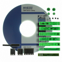
Description
KIT EVALUATION GT SENSOR
Manufacturer
NVE
Specifications of AG920-07E
Sensor Type
Magnetic. GMR (Giant Magnetoresistive)
Interface
Analog
Embedded
No
Utilized Ic / Part
ABL & AKL Series GT Sensors
Lead Free Status / RoHS Status
Lead free / RoHS Compliant
Voltage - Supply
-
Sensitivity
-
Sensing Range
-
Other names
391-1063


The figure below shows another configuration where a current trace on a PCB is under the board-
mounted sensor.
An Excel spreadsheet is available on NVE’s web site which helps calculate the magnetic field at the
sensor from a current carrying trace on the board as shown in the diagram above.
Principles of Operation
The magnetic field created by the current surrounds the conductor radially. As the magnetic field
affects the GMR material in the sensor, a differential output is produced at the out pins of the sensor.
The magnetic field strength is directly proportional to the current flowing through the conductor. As
the current increases, the surrounding magnetic field will also increase, thus increasing the output from
the sensor. Similarly, as the current decreases, the magnetic field and sensor output decrease.
Since the current is not measured directly, the sensor output must be correlated to the current. The
following data and graphs are based upon analysis of NVE’s evaluation board contained in our current
sensor evaluation kit, part number AG003-01. The PCB contains four traces of three different widths:
90 mils, 60 mils, and 10 mils.
S
ENSING
Current carrying
M
PCB trace
AGNETIC
www.nve.com
F
IELD FROM A
phone: 952-829-9217 fax: 952-829-9189
AAxxx-xx
NVE
- 118 -
C
URRENT
C
Application Notes
ARRYING
Axis of Sensitivity
PCB T
PCB
RACE
Related parts for AG920-07E
Image
Part Number
Description
Manufacturer
Datasheet
Request
R

Part Number:
Description:
KIT EVALUATION GT SENSOR
Manufacturer:
NVE
Datasheet:

Part Number:
Description:
ISOLATOR HS MAG DIGITAL 8SOIC
Manufacturer:
NVE
Datasheet:
Part Number:
Description:
ISOLATOR HS DIGITAL 125C 8SOIC
Manufacturer:
NVE
Datasheet:

Part Number:
Description:
HI-SPD 4CHANN COUPLER 16-SOIC LF
Manufacturer:
NVE
Datasheet:
Part Number:
Description:
ISOLATOR HS MAG DIGITAL 16SOIC
Manufacturer:
NVE
Datasheet:
Part Number:
Description:
ISOLATOR HS MAG DIGITAL 8SOIC
Manufacturer:
NVE
Datasheet:
Part Number:
Description:
IC DIFFER BUS TRANSC 16 SOIC
Manufacturer:
NVE
Datasheet:
Part Number:
Description:
ISOLATOR HS MAG DIGITAL 16SOICW
Manufacturer:
NVE
Datasheet:

Part Number:
Description:
ISOLATOR RS422/485 INTFC 16SOICW
Manufacturer:
NVE
Datasheet:
Part Number:
Description:
ISOLATOR HS MAG DIGITAL 16SOICW
Manufacturer:
NVE
Datasheet:

Part Number:
Description:
IC, DIGITAL ISOLATOR, 12NS, NSOIC-8
Manufacturer:
NVE
Datasheet:

Part Number:
Description:
IC, DIGITAL ISOLATOR, 12NS, DIP-8
Manufacturer:
NVE
Datasheet:
Part Number:
Description:
IC TXRX ISOLATED CAN HS 16SOIC
Manufacturer:
NVE
Datasheet: