AG920-07E NVE, AG920-07E Datasheet - Page 42
AG920-07E
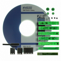
Manufacturer Part Number
AG920-07E
Description
KIT EVALUATION GT SENSOR
Manufacturer
NVE
Specifications of AG920-07E
Sensor Type
Magnetic. GMR (Giant Magnetoresistive)
Interface
Analog
Embedded
No
Utilized Ic / Part
ABL & AKL Series GT Sensors
Lead Free Status / RoHS Status
Lead free / RoHS Compliant
Voltage - Supply
-
Sensitivity
-
Sensing Range
-
Other names
391-1063


Output Transistor Current in Short Circuit mode:
Notes:
1.
2.
3.
4.
5.
Magnetic Characteristics:
Note: All Values in Oersteds (Oe); 1 Oe = 1 Gauss in Air
Typical Operate
The t
startup transients: see t
The t
for a 15 ms Off time.
The voltage across R
Typical value of R
R
supply 1 mA drive to the output transistor.
R
300
200
100
BIAS1
LED
Point
is sized for whatever LED current is required by the user (maximum of 3 mA.)
20
28
40
80
2
1
and R
Capacitor is used to delay the startup of the SCP circuitry in order to avoid triggering the SCP circuitry on normal
Capacitor is used to set the “Off” time of the SCP circuitry; see t
BIAS2
t
2
are used to bias the output transistor. Typical values for R
SHORT
SHORT
Operate Point
2
is 0.47Ω, 1/16 watt. This will result in SCP circuitry turning on at about 300 mA of output current.
Minimum
on the graph above. Typical value is 16V, 0.001µF, for a 35µs delay.
is monitored by the IC. If this voltage exceeds 145 mV (typical), the SCP circuitry is activated.
www.nve.com
15
21
30
60
Output Transistor Current in Short Circuit
t
1
Operate Point
phone: 952-829-9217 fax: 952-829-9189
Maximum
GMR Switch Precision Digital Sensors
100
25
34
50
Time
- 42 -
Differential
Minimum
1
on the graph above. Typical value is 16V, 0.01µF,
BIAS1
5
5
5
5
and R
1,2
BIAS2
are 16kΩ and 3kΩ, respectively, to
Differential
Maximum
14
20
25
35
1,2
Related parts for AG920-07E
Image
Part Number
Description
Manufacturer
Datasheet
Request
R

Part Number:
Description:
KIT EVALUATION GT SENSOR
Manufacturer:
NVE
Datasheet:

Part Number:
Description:
ISOLATOR HS MAG DIGITAL 8SOIC
Manufacturer:
NVE
Datasheet:
Part Number:
Description:
ISOLATOR HS DIGITAL 125C 8SOIC
Manufacturer:
NVE
Datasheet:

Part Number:
Description:
HI-SPD 4CHANN COUPLER 16-SOIC LF
Manufacturer:
NVE
Datasheet:
Part Number:
Description:
ISOLATOR HS MAG DIGITAL 16SOIC
Manufacturer:
NVE
Datasheet:
Part Number:
Description:
ISOLATOR HS MAG DIGITAL 8SOIC
Manufacturer:
NVE
Datasheet:
Part Number:
Description:
IC DIFFER BUS TRANSC 16 SOIC
Manufacturer:
NVE
Datasheet:
Part Number:
Description:
ISOLATOR HS MAG DIGITAL 16SOICW
Manufacturer:
NVE
Datasheet:

Part Number:
Description:
ISOLATOR RS422/485 INTFC 16SOICW
Manufacturer:
NVE
Datasheet:
Part Number:
Description:
ISOLATOR HS MAG DIGITAL 16SOICW
Manufacturer:
NVE
Datasheet:

Part Number:
Description:
IC, DIGITAL ISOLATOR, 12NS, NSOIC-8
Manufacturer:
NVE
Datasheet:

Part Number:
Description:
IC, DIGITAL ISOLATOR, 12NS, DIP-8
Manufacturer:
NVE
Datasheet:
Part Number:
Description:
IC TXRX ISOLATED CAN HS 16SOIC
Manufacturer:
NVE
Datasheet: