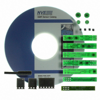
AG920-07E NVE, AG920-07E Datasheet - Page 121

AG920-07E
Manufacturer Part Number
AG920-07E
Description
KIT EVALUATION GT SENSOR
Manufacturer
NVE
Specifications of AG920-07E
Sensor Type
Magnetic. GMR (Giant Magnetoresistive)
Interface
Analog
Embedded
No
Utilized Ic / Part
ABL & AKL Series GT Sensors
Lead Free Status / RoHS Status
Lead free / RoHS Compliant
Voltage - Supply
-
Sensitivity
-
Sensing Range
-
Other names
391-1063
- Current page: 121 of 143
- Download datasheet (2Mb)
Another magnetic contribution to the error can be overcome by an initialization current. Often,
depending on the magnetic history (hysteresis) of the sensor, the initial outputs are different from
subsequent outputs as seen in the figure below:
The initial sweep data has deviated from the other series of current sweeps. After the first sweep was
completed, the subsequent five sweeps fell right on each other. This shows that a lower error can be
obtained by “initializing” the sensor. After initialization, the error will be much lower until the
working current range is exceeded in either direction. Saturation of the device (currents in the 20A
range) as well as changing the applied current direction will increase the hysteresis/error.
For currents of approximately 2 Amps and smaller, the output repeatability is nominally 2% while
higher currents produce output repeatability errors of less than 1%. Low current measurements of an
initial current sweep may exceed 15% error in repeatability.
DATA ANALYSIS- Low Current Sensing
The low current analysis is handled here separately from the higher current analysis due to special
considerations that must be made, although much of the same hysteresis and resolution considerations
from high field sensing apply here. For low current sensing, two configurations of 0.010" wide traces
were used. The first analysis will be with an AA003-02 sensor over a single 10-mil trace and the
second analysis will consist of an AA003-02 sensor over seven 10-mil traces. With these traces,
milliamp and sub-milliamp currents are of interest. Due to the hysteresis at low currents as discussed
above, a biasing magnet was used to set the parts to approximately half of their linear range, or
approximately 20 mV/V. This bias point can be seen as the Y intercept in the figures below. In this
way, the output will not be near the natural zero current range, and thus, repeatability is increased.
With this configuration an alternating sense current will produce a bipolar output with a DC offset in
an AC application.
300
250
200
150
100
50
0
www.nve.com
0
Initialization of AA003-02
2
phone: 952-829-9217 fax: 952-829-9189
- 121 -
4
Current ( A )
6
Initial sweep
Series2
Series3
Series4
Series5
Series6
Application Notes
8
10
Related parts for AG920-07E
Image
Part Number
Description
Manufacturer
Datasheet
Request
R

Part Number:
Description:
KIT EVALUATION GT SENSOR
Manufacturer:
NVE
Datasheet:

Part Number:
Description:
ISOLATOR HS MAG DIGITAL 8SOIC
Manufacturer:
NVE
Datasheet:

Part Number:
Description:
ISOLATOR HS DIGITAL 125C 8SOIC
Manufacturer:
NVE
Datasheet:

Part Number:
Description:
HI-SPD 4CHANN COUPLER 16-SOIC LF
Manufacturer:
NVE
Datasheet:

Part Number:
Description:
ISOLATOR HS MAG DIGITAL 16SOIC
Manufacturer:
NVE
Datasheet:

Part Number:
Description:
ISOLATOR HS MAG DIGITAL 8SOIC
Manufacturer:
NVE
Datasheet:

Part Number:
Description:
IC DIFFER BUS TRANSC 16 SOIC
Manufacturer:
NVE
Datasheet:

Part Number:
Description:
ISOLATOR HS MAG DIGITAL 16SOICW
Manufacturer:
NVE
Datasheet:

Part Number:
Description:
ISOLATOR RS422/485 INTFC 16SOICW
Manufacturer:
NVE
Datasheet:

Part Number:
Description:
ISOLATOR HS MAG DIGITAL 16SOICW
Manufacturer:
NVE
Datasheet:

Part Number:
Description:
IC, DIGITAL ISOLATOR, 12NS, NSOIC-8
Manufacturer:
NVE
Datasheet:

Part Number:
Description:
IC, DIGITAL ISOLATOR, 12NS, DIP-8
Manufacturer:
NVE
Datasheet:

Part Number:
Description:
IC TXRX ISOLATED CAN HS 16SOIC
Manufacturer:
NVE
Datasheet:


