STM3210C-EVAL STMicroelectronics, STM3210C-EVAL Datasheet
STM3210C-EVAL
Specifications of STM3210C-EVAL
Available stocks


Related parts for STM3210C-EVAL


STM3210C-EVAL Summary of contents
Page 1
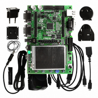
... Introduction The STM32F107VCT evaluation board STM3210C-EVAL is designed as a complete development platform for STMicroelectronic's ARM Cortex-M3 core-based STM32F107VCT microcontroller with full speed USB-OTG, ethernet MAC, two channels of CAN2.0A/B compliant interface, 2 channels I2S, 2 channels I2C, 5 channels USART with smartcard support, 3 channels SPI, internal 64 KB SRAM and 256 KB Flash, JTAG and SWD debugging support ...
Page 2
Contents Contents 1 Overview . . . . . . . . . . . . . . . . . . . . . . . . . . . . . . . . . . . . ...
Page 3
... Daughterboard extension connector CN8 and CN9 . . . . . . . . . . . . . . . . . 24 3.9 Audio jack CN7 . . . . . . . . . . . . . . . . . . . . . . . . . . . . . . . . . . . . . . . . . . . . . 27 3.10 TFT LCD connector CN14 . . . . . . . . . . . . . . . . . . . . . . . . . . . . . . . . . . . . 27 3.11 MicroSD card connector CN16 . . . . . . . . . . . . . . . . . . . . . . . . . . . . . . . . . 28 3.12 USB MicroAB connector CN2 . . . . . . . . . . . . . . . . . . . . . . . . . . . . . . . . . 28 3.13 Power connector CN18 . . . . . . . . . . . . . . . . . . . . . . . . . . . . . . . . . . . . . . 29 3.14 Smartcard connector CN5 . . . . . . . . . . . . . . . . . . . . . . . . . . . . . . . . . . . . 29 4 Schematics . . . . . . . . . . . . . . . . . . . . . . . . . . . . . . . . . . . . . . . . . . . . . . . 30 Appendix A STM3210C-EVAL I/O assignment . . . . . . . . . . . . . . . . . . . . . . . . . . . 48 Revision history . . . . . . . . . . . . . . . . . . . . . . . . . . . . . . . . . . . . . . . . . . . . . . . . . . . . 51 Doc ID 15082 Rev 3 Contents 3/52 ...
Page 4
... Demonstration software is preloaded in the board’s Flash memory for easy demonstration of device peripherals in stand-alone mode. For more information and to download the latest version available, please refer to STM3210C-EVAL demonstration firmware available on the web: www.st.com/mcu. 1.3 Order code To order the STM32F107VCT evaluation board, use the order code STM3210C-EVAL. 4/ Doc ID 15082 Rev 3 UM0600 ...
Page 5
... UM0600 2 Hardware layout and configuration The STM3210C-EVAL evaluation board is designed around the STM32F107VCT in a 100- pin LQFP package. The hardware block diagram the STM32F107VCT and peripherals (LCD, EEPROM, MEMS, USART, IrDA, USB-OTG, ethernet, audio, CAN bus, smartcard, microSD card and motor control) and you locate these features on the actual evaluation board ...
Page 6
... Hardware layout and configuration Figure 3. STM3210C-EVAL evaluation board layout CN10, CN11 BNC CN4 CAN2 CN3 CAN1 CN18 5V power CN7 Audio jack CN16 MicroSD card CN5 Smartcard B1 Reset 6/52 CN8, CN9 Extension header U9 STM32F107VCT B2 Wakeup B4 Tamper Doc ID 15082 Rev 3 CN17 Motor control ...
Page 7
... UM0600 2.1 Power supply The STM3210C-EVAL evaluation board is designed to be powered power supply and to be protected by PolyZen from a wrong power plug-in event possible to configure the evaluation board to use any of following three sources for the power supply power adapter connected to CN18, the power jack on the board (PSU on silk screen for power supply unit) ...
Page 8
... Kohm) in series and IDD current measurement circuit in parallel when JP23 is set as shown to the right. MCU power consumption measurement is enabled. The LED LD7 is lit when the STM3210C-EVAL board is powered by the 5 V correctly. 8/52 When the board is connected to an USB host via CN2 and ...
Page 9
... X3, 25 MHz crystal with socket for an STM32F107VCT microcontroller, it can be removed from the socket when an internal RC clock is used. 2.4 Reset source The reset signal of the STM3210C-EVAL board is active low and the reset sources include: Reset button, B1 Debugging tools from JTAG connector CN13 and trace connector CN12 Daughterboard from CN9 RS-232 connector CN6 for ISP when JP19 is fitted ...
Page 10
... Hardware layout and configuration 2.5 Audio The STM3210C-EVAL evaluation board supports stereo audio play by using an audio DAC CS43L22 connected to both an I2S2 port and one channel of the DAC of microcontroller STM32F107VCT. The CS43L22 can be configured via the I2C1 bus when JP9 is fitted (default setting). The automatic switch between the speaker and headphone is performed by both CS43L22 and the audio jack with plug detection pin ...
Page 11
... RS-232 and IrDA Both RS-232 and IrDA communications are supported by D-type 9-pin RS-232 connectors CN6 and IrDA transceiver U12 which connect to USART2 of the STM32F107VCT on the STM3210C-EVAL evaluation board. Two signals, Bootloader_BOOT0 and Bootloader_RESET, are added on the RS-232 connector for ISP support. ...
Page 12
... Hardware layout and configuration 2.9 Motor control The STM3210C-EVAL evaluation board supports a three-phase brushless motor control via a 34-pin connector CN17, which provides all required control and feedback signals to and from a motor power-driving board. Available signals on this connector include emergency stop, motor speed, 3 phase motor current, bus voltage, heat sink temperature from the motor driving board and 6 channels of PWM control signal going to the motor driving circuit ...
Page 13
... UM0600 2.10 Smartcard STMicroelectronic’s smartcard interface chip ST8024 is used on the STM3210C-EVAL board for asynchronous 3 V and 5 V smartcards. It performs all supply protection and control functions based on the connections with the STM32F107VCT listed in Table 10. Connection between the ST8024 and STM32F107VCT Signals of ...
Page 14
Hardware layout and configuration 2.11 MicroSD card The 2 GByte (or more) microSD card connected to SPI3 of STM32F107VCT is available on the board. MicroSD card detection is managed by the standard I/O port PE0. JP15 must remain fitted to ...
Page 15
... LED LD6 is lit: in Host mode when the power switch (U3 (STM3210C-EVAL is acting as a USB host), in Device mode when a cable is connected (STM3210C-EVAL is acting as a USB device and VBUS is powered by another USB host). LD5 is lit when over-current occurs in Host mode. Hardware layout and configuration ...
Page 16
... An ST MEMS device LIS302DL is connected to the I2C1 bus of STM32F107VCT. 2.16 Development and debug support The two debug connectors available on STM3210C-EVAL evaluation board are: 1. CN13, standard 20-pin JTAG interface connector that is compliant with the debug tools of ARM7 and ARM9 and cortex M3. ...
Page 17
... JP14 should be re-configured to enable wakeup button B2 which shares the same I/O as MII_CRS of the ethernet. You may refer to The STM3210C-EVAL board also supports a second optional 2.4” TFT LCD without touch screen that can be mounted on CN15 connector. The 2.4” TFT LCD is not populated by default ...
Page 18
... IDD measurement Figure 4. STM3210C-EVAL IDD measurement circuit The circuit above is implemented on STM3210C-EVAL for IDD measurement. In Run mode, IDD current is measured using MAX9938FEUK+ (U21) connected to the 1ohm shunt resistor. In this case IDD_CNT_EN remains high during measurement and JP23 jumper must be set to 2<->3. ...
Page 19
... UM0600 Figure 5. STM3210C-EVAL IDD Low power mode measurement timing diagram Run MCU mode 0 IDD_CNT_EN Q13=LOW_POWER_EN (T2 pin 3) Q14=LP_WAKEUP Q14n=Switch control (U22 pin 4) The Low power mode measurement procedure can be used in Stop or Standby modes if the IDD current does not exceed 60 uA, otherwise the Run mode measurement procedure should be used ...
Page 20
Connectors 3 Connectors 3.1 Motor control connector CN17 Figure 6. Motor control connector CN17 viewed from above the PCB Table 15. Motor control connector CN17 Description Emergency stop PWM-UH PWM-UL PWM-VH PWM-VL PWM-WH PWM-WL PHASE A current PHASE B current ...
Page 21
UM0600 3.2 Analog input connector CN10 and CN11 Figure 7. Analog input connector CN10 and CN11 viewed from the bottom Table 16. Analog input connector CN10 and CN11 Pin number 3.3 CAN D-type 9-pin male connector CN3 ...
Page 22
Connectors 3.4 Ethernet RJ45 connector CN1 Figure 9. Ethernet RJ45 connector CN1 viewed from the front Table 18. RJ45 connector CN1 Pin number 3.5 Trace debugging connector CN12 Figure 10. Trace debugging connector CN12 viewed from ...
Page 23
UM0600 3.6 RS-232 connector CN6 Figure 11. RS-232 connector CN6 with ISP support viewed from the front Table 20. RS-232 connector CN6 with ISP support Pin number 3.7 JTAG debugging connector CN13 Figure 12. JTAG ...
Page 24
... Daughterboard extension connector CN8 and CN9 Two 50-pin male headers CN8 and CN9 can be used to connect a daughterboard or standard wrapping board to the STM3210C-EVAL evaluation board. All 80 GPI/Os are available on it. The space between these two connectors and power position, GND and RESET pin are defined as a standard, which allows to develop common daughterboards for several evaluation boards ...
Page 25
... JP4 open Remove R38 or disconnect USB cable Remove R42 or disconnect USB cable Remove R135 and LCD Remove R44 Disconnect STM3210C-EVAL board from motor power drive board. Remove R97 Keep JP16 open Keep JP20 open Remove MicroSD card. Disconnect STM3210C-EVAL board from motor power drive board ...
Page 26
... Remove R69 Remove R168 Remove R154 Remove R169 Keep JP15 open Remove R162 Remove RS1 Keep JP1 open Disconnect STM3210C-EVAL board from motor power drive board Remove R95 Remove RS1 Keep JP12 open Keep JP13 open Remove R159 Doc ID 15082 Rev 3 UM0600 ...
Page 27
... MB785. Please refer to How to disconnect with component on STM3210C-EVAL board Remove RS3 Remove RS2 Remove R139 Disconnect STM3210C-EVAL board from motor power drive board Disconnect STM3210C-EVAL board from motor power drive board Remove R168 Remove R167 Remove R103 Remove R79 Remove R84 ...
Page 28
Connectors 3.11 MicroSD card connector CN16 Figure 13. MicroSD card connector CN16 viewed from the front Table 24. MicroSD card connector CN16 Pin number 1 2 MicroSDcard_CS (PA4) 3 MicroSDcard_DIN(PC12) 4 +3V3 5 MicroSDcard_CLK (PC10) 3.12 USB MicroAB connector CN2 ...
Page 29
... UM0600 3.13 Power connector CN18 Your STM3210C-EVAL evaluation board can be powered from power supply via the external power supply jack (CN18) shown in positive. Figure 15. Power supply connector CN18 viewed from the front 3.14 Smartcard connector CN5 Figure 16. Smartcard connector CN5 Table 26. ...
Page 30
... Schematics 4 Schematics This section provides the following schematics: Figure 17: STM3210C on page 31 Figure 18: MCU on page 32 Figure 19: Ethernet on page 33 Figure 20: Full speed USB-OTG on page 34 Figure 21: Audio on page 35 Figure 22: LCD on page 36 Figure 23: I/O expander on page 37 Figure 24: CAN on page 38 Figure 25: RS-232 and IrDA on page 39 Figure 26: Smartcard on page 40 ...
Page 31
... TouchScreen_Y+ TouchScreen_X- TouchScreen_X+ TouchScreen_Y- TouchScreen_Y+ TouchScreen_X- TouchScreen_X+ Note1: only decoupling capacitors value was updated from Versioin B.1 to B.2. Note2: only assembly request of R42 and R43 was updated from Versioin B.2 to B.3. STMicroelectronics Title: STM3210C-EVAL Number: MB784 Rev: B.3(PCB.SCH) Date: 9/18/2009 Sheet ...
Page 32
... TRACE_D0 JP15: close / SDcard CS open / output for audio DAC TRACE_CK JP18: open/ BL_Boot0 disabled close / BL_Boot0 USB_OverCurrent JP19: open/ BL_Reset disabled close / BL_Reset MC_PFCsync2 STMicroelectronics Title: STM3210C-EVAL MCU Number: MB784 Rev: B.3(PCB.SCH) Date: 10/10/2009 3 4 PA[0..15] PB[0..15] PC[0..15] PD[0..15] PE[0..15] Sheet 2 ...
Page 33
... JP2 open close 36 JP3 2<->3 1<->2 JP4 2<->3 2<->3 External 25MHz crystal mode ===================== C7 C8 JP4 1<->2 (MCO pin free for another 100nF 100nF application) STMicroelectronics Title: STM3210C-EVAL Ethernet Number: MB784 Rev: B.3(PCB.SCH) Date: 9/18/2009 Sheet 3 ...
Page 34
... TPS2041BDBV 4.7uF R42 22 R43 Vbus D+out D+ D-out D- Pd1 B2 C2 Pup Pd2 D2 GND EMIF02-USB03F2 2 USB_OverCurrent PE1 CN2 1 VBUS GND 0 Shield 475900001 +3V3 R39 330 LD6 Green 9013 47K R5 [N/A] STMicroelectronics Title: STM3210C-EVAL USB_OTG_FS Number: MB784 Rev: B.3(PCB.SCH) Date: 9/18/2009 3 4 Sheet 4 of ...
Page 35
... CS43L22 C49 I2C address 0x94 1uF 2 3 +2V5 R75 C44 47K 0.022uF CN7 ST-212-02V +5V C38 100nF C95 R80 R83 Audio_DAC_OUT 100 0 1uF R81 100K C50 C93 C94 1uF 150pF(COG) 150pF(COG) STMicroelectronics Title: STM3210C-EVAL Audio Number: MB784 Rev: B.3(PCB.SCH) Date: 9/18/2009 4 Sheet ...
Page 36
... LCD_connector (MB785 with AM-240320D4TOQW-T00H(R)) CN15 SCL 3 SDI SDO 8 RESET 9 +3V3 VDD 10 VCI 11 GND 12 GND 13 +3V3 BL_VDD 14 BL_Control 15 BL_GND 16 BL_GND 2.4" LCD connector (MB542 with AM240320L8TNQW-00H expandor TouchScreen_X- TouchScreen_X+ TouchScreen_Y- TouchScreen_Y+ STMicroelectronics Title: STM3210C-EVAL LCD Number: MB784 Rev: B.3(PCB.SCH) Date: 9/18/2009 3 4 Sheet 6 of ...
Page 37
... A0/Data Out IN0 10K R164 R56 STMPE811 10K 10K I2C device address:0x88 R58 +3V3 100K +3V3 2 EXP_IO9 EXP_IO10 EXP_IO11 EXP_IO12 EXP_IO1 EXP_IO2 EXP_IO3 EXP_IO4 EXP_IO5 EXP_IO6 EXP_IO7 EXP_IO8 STMicroelectronics Title: STM3210C-EVAL IO_Expandor Number: MB784 Rev: B.3(PCB.SCH) Date: 9/18/2009 3 4 Sheet 7 of ...
Page 38
... Default setting: 1<->2 Default setting: Open JP8 JP6 GND CANH VCC CANL Vref R53 4 SN65HVD230 120 9 5 R55 R51 [N/A] 0 +3V3 2 CN3 DB9-male CAN connector CN4 DB9-male CAN connector STMicroelectronics Title: STM3210C-EVAL CAN Number: MB784 Rev: B.3(PCB.SCH) Date: 9/18/2009 3 4 Sheet 8 of ...
Page 39
... Cathode R77 6 VCC1 7 47 Vlogic 8 GND TFDU4300 C35 C36 C28 C29 4.7uF 4.7uF 100nF 100nF IrDA 2 C34 CN6 100nF DB9-male UART4 DCD 1 6 RXD 2 7 TXD 3 CTS STMicroelectronics Title: STM3210C-EVAL RS232&IrDA Number: MB784 Rev: B.3(PCB.SCH) Date: 9/18/2009 3 4 Sheet 9 of ...
Page 40
... NC NC CN5 17 C816 R70 18 +3V3 100K 2 PC0 SmartCard_3/5V TP2 AUX2 TP3 AUX1 PD8 SmartCard_IO PD10 SmartCard_CLK PE7 SmartCard_OFF +3V3 C26 C23 10uF 100nF PD9 SmartCard_RST PE14 SmartCard_CMDVCC STMicroelectronics Title: STM3210C-EVAL Smart card Number: MB784 Rev: B.3(PCB.SCH) Date: 9/18/2009 3 4 Sheet 10 of ...
Page 41
... PA5 BUS VOLTAGE MC_BusVoltage GND 18 C62 R145 GND 20 100nF 100K GND 22 GND 24 GND R142 R85 26 PC0 MC_HeatsinkTemperature Vdd_Micro +3V3 30 C63 GND 32 100nF GND 34 Encoder Index PC8 MC_EnIndex C67 [N/A] STMicroelectronics Title: STM3210C-EVAL Motor control Number: MB784 Rev: B.3(PCB.SCH) Date: 9/18/2009 4 Sheet ...
Page 42
... PB6 14 5 MEMS_SCK SCL GND 8 4 MEMS_INT1 INT1 GND 9 11 MEMS_INT2 INT2 Reserved To IO expandor LIS302DL +3V3 R103 R86 PC4 2 RV1 Potentiometer 10K 0 1K C60 10nF Potentiometer STMicroelectronics Title: STM3210C-EVAL IO Peripherals Number: MB784 Rev: B.3(PCB.SCH) Date: 9/18/2009 Sheet 3 4 LEDs MEMS ...
Page 43
... PB0 33 34 PC4 35 36 PA6 37 38 PA5 39 40 PA3 41 42 PA1 43 44 PC2 45 46 PC0 Header 25X2 PA[0..15] PA[0..15] PB[0..15] PB[0..15] PC[0..15] PC[0..15] PD[0..15] PD[0..15] PE[0..15] PE[0..15] RESET# RESET# STMicroelectronics Title: STM3210C-EVAL Extension connector Number: MB784 Rev: B.3(PCB.SCH) Date: 9/18/2009 Sheet ...
Page 44
... PA13 PA14 PB3 PA15 PB4 R125 10K CN13 JTAG +3V3 +3V3 R127 10K 18 19 R128 10K 20 JTAG connector PE6 PE5 PE4 PE3 PE2 2 JP20 R118 [N/A] R126 10K STMicroelectronics Title: STM3210C-EVAL JTAG & Trace Number: MB784 Rev: B.3(PCB.SCH) Date: 9/18/2009 3 Sheet ...
Page 45
... Figure 31. MicroSD card +3V3 R138 4K7 PC11 R135 0 MicroSDCard_MISO PC10 MicroSDCard_SCK +3V3 PC12 MicroSDCard_MOSI PA4 R136 0 MicroSDCard_CS CN16 PJS008-2000 SMS064FF or SMS128FF R137 PE0 MicroSDCard_Detection 0 MicroSD card STMicroelectronics Title: STM3210C-EVAL MicroSD card Number: MB784 Rev: B.3(PCB.SCH) Date: 9/18/2009 Sheet 15 of ...
Page 46
... CG1 10uF 5 CG2 Z1 6 CG3 SMAJ5.0A-TR C77 100nF BNX002-01 TP10 TP11 3V3 D5V E5V 5V +3V3 JP25 C75 C80 USB_VBUS 2 1 10uF 100nF LD7 R148 2 1 1K5 red STMicroelectronics Title: STM3210C-EVAL Power Number: MB784 Rev: B.3(PCB.SCH) Date: 9/18/2009 3 4 +5V TP12 Ground Sheet ...
Page 47
... D12 17 PD13 10K D13 16 PD14 RP4 D14 15 PD15 PD17 D15 14 PD16 PD15 D16 13 PD17 PD13 D17 PD11 10K RP5 PD7 PD5 VDD PD3 PD1 10K C3 1uF/50V STMicroelectronics Title: 3.2" LCD module with both SPI & 1 Number: MB785 Rev: A.1(PCB.SCH) Date: 3/27/2009 ...
Page 48
... PA0-WKUP 24 PA1 25 PA2 26 PA3 27 VSS_4 28 VDD_4 29 PA4 30 PA5 31 PA6 32 PA7 48/52 STM3210C-EVAL I/O assignment Trace_CK Trace_D0 Trace_D1 Trace_D2 Trace_D3 Battery Anti-tamper button / IDD_CNT_EN 32K OSC GND +3V3 25MHz OSC 25MHz OSC RESET# MC_ADC10 pin 26 (heatsinktemp) / SmartCard_3/5V ETHER_MDC ETHER_TXD2 ETHER_TX_CLK GND GND ...
Page 49
... UM0600 Table 27. STM3210C-EVAL I/O assignment (continued) Pin No. Pin name 33 PC4 34 PC5 35 PB0 36 PB1 37 PB2 38 PE7 39 PE8 40 PE9 41 PE10 42 PE11 43 PE12 44 PE13 45 PE14 46 PE15 47 PB10 48 PB11 49 VSS_1 50 VDD_1 51 PB12 52 PB13 53 PB14 54 PB15 55 PD8 56 PD9 57 PD10 58 PD11 59 PD12 60 PD13 61 PD14 62 PD15 63 PC6 64 PC7 ...
Page 50
... STM3210C-EVAL I/O assignment Table 27. STM3210C-EVAL I/O assignment (continued) Pin No. Pin name 68 PA9 69 PA10 70 PA11 71 PA12 72 PA13 VSS_2 75 VDD_2 76 PA14 77 PA15 78 PC10 79 PC11 80 PC12 81 PD0 82 PD1 83 PD2 84 PD3 85 PD4 86 PD5 87 PD6 88 PD7 89 PB3 90 PB4 91 PB5 92 PB6 93 PB7 94 BOOT0 95 PB8 96 PB9 97 PE0 98 PE1 ...
Page 51
UM0600 Revision history Table 28. Document revision history Date 26-Feb-2009 19-Jun-2009 16-Oct-2009 Revision 1 Initial release 2 Update for PCB rev.B 3 Update to make schematics searchable Doc ID 15082 Rev 3 Revision history Changes 51/52 ...
Page 52
... Information in this document is provided solely in connection with ST products. STMicroelectronics NV and its subsidiaries (“ST”) reserve the right to make changes, corrections, modifications or improvements, to this document, and the products and services described herein at any time, without notice. All ST products are sold pursuant to ST’s terms and conditions of sale. ...