STM3210C-EVAL STMicroelectronics, STM3210C-EVAL Datasheet - Page 15
STM3210C-EVAL
Manufacturer Part Number
STM3210C-EVAL
Description
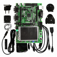
EVAL BOARD FOR STM32F107VCT
Manufacturer
STMicroelectronics
Type
MCUr
Datasheets
1.STM3210C-EVAL.pdf
(21 pages)
2.STM3210C-EVAL.pdf
(5 pages)
3.STM3210C-EVAL.pdf
(52 pages)
Specifications of STM3210C-EVAL
Contents
Fully Assembled Evaluation Board
Processor To Be Evaluated
STM32F107VCT
Processor Series
STM32
Interface Type
RS-232, USB, I2C, JTAG
Operating Supply Voltage
5 V
For Use With/related Products
STM32F107
Lead Free Status / RoHS Status
Lead free / RoHS Compliant
Other names
497-8924
Available stocks
Company
Part Number
Manufacturer
Quantity
Price
Company:

Part Number:
STM3210C-EVAL
Manufacturer:
STMicroelectronics
Quantity:
135
Company:
Part Number:
STM3210C-EVAL
Manufacturer:
STMicroelectronics
Quantity:
1


UM0600
2.13
Note:
2.14
Ethernet
The STM3210C-EVAL evaluation board supports 10M/100M ethernet communication by a
PHY DP83848CVV (U1) and integrated RJ45 connector (CN1). Both MII and RMII interface
modes are supported and can be selected by setting jumpers JP2, JP3 and JP4.
Table 13.
JP11, JP12, JP13 and JP14 are set to support ethernet by default, please verify the jumper
configuration before ethernet demonstration.
Note2: Test point TP1 is connected to 25MHz clock output pin of Ethernet PHY U1 which
provide 25MHz or 50MHz clock for system in MII or RMII mode.
Note3: Test point TP4 can be used for PTP_PPS feature only when R45 is removed.
USB-OTG
The STM3210C-EVAL evaluation board supports USB-OTG full speed communication via a
USB MicroAB connector (CN2) and a USB power switch (U3) connected to VBUS.
The evaluation board can be powered by this USB connection at 5 V DC with a 500 mA
current limitation.
LED LD6 is lit:
LD5 is lit when over-current occurs in Host mode.
JP2
JP3
JP4
Jumper
in Host mode when the power switch (U3) is ON (STM3210C-EVAL is acting as a USB
host),
in Device mode when a cable is connected to a PC (STM3210C-EVAL is acting as a
USB device and VBUS is powered by another USB host).
JP2 selects MII or RMII interface mode. MII is enabled when JP2 is open
while RMII interface mode is enabled when JP2 is fitted. Default setting:
Not fitted.
JP3 should be set as shown when MII interface mode is enabled.
(Default)
JP3 should be set as shown when RMII interface mode is enabled.
25 MHz clock for MII or 50 MHz clock for RMII is provided by MCO at
PA8 when JP4 is set as shown: (Default)
25 MHz clock is provided by external crystal X1 (for MII interface mode
only) when JP4 is set as shown:
JP4 has to be kept open when the clock is provided by external oscillator
U2 (not fitted by default).
Ethernet related jumpers
Doc ID 15082 Rev 3
Description
Hardware layout and configuration
Configuration
1 2 3
1 2 3
1 2 3
1 2 3
15/52
Related parts for STM3210C-EVAL
Image
Part Number
Description
Manufacturer
Datasheet
Request
R

Part Number:
Description:
DEV KIT FOR STM32
Manufacturer:
STMicroelectronics
Datasheet:

Part Number:
Description:
DEV KIT FOR STM32
Manufacturer:
STMicroelectronics
Datasheet:

Part Number:
Description:
DEV KIT FOR STM32
Manufacturer:
STMicroelectronics
Datasheet:

Part Number:
Description:
DEV KIT FOR STM32
Manufacturer:
STMicroelectronics
Datasheet:

Part Number:
Description:
MCU ARM 128KB FLASH MEM 64-LQFP
Manufacturer:
STMicroelectronics
Datasheet:

Part Number:
Description:
MCU ARM 32BIT 128KB FLASH 64BGA
Manufacturer:
STMicroelectronics
Datasheet:

Part Number:
Description:
MCU ARM 32BIT 256K FLASH 144LQFP
Manufacturer:
STMicroelectronics
Datasheet:

Part Number:
Description:
KIT STARTER FOR STM32F10X
Manufacturer:
STMicroelectronics
Datasheet:

Part Number:
Description:
MCU ARM 128K FLASH/TIMER
Manufacturer:
STMicroelectronics
Datasheet:

Part Number:
Description:
MCU ARM 128KB FLASH MEM 100-LQFP
Manufacturer:
STMicroelectronics
Datasheet:

Part Number:
Description:
MCU 32BIT ARM 64K FLASH 36VFQFPN
Manufacturer:
STMicroelectronics
Datasheet:
Part Number:
Description:
MCU ARM 32BIT 32KB FLASH 48LQFP
Manufacturer:
STMicroelectronics
Datasheet:
Part Number:
Description:
MCU ARM 32BIT 64KB FLASH 64LQFP
Manufacturer:
STMicroelectronics
Datasheet:
Part Number:
Description:
MCU ARM 32BIT 384KB FLASH 64LQFP
Manufacturer:
STMicroelectronics
Datasheet:

Part Number:
Description:
MCU 32BIT ARM 512K FLASH 100-LQF
Manufacturer:
STMicroelectronics
Datasheet: