STM3210C-EVAL STMicroelectronics, STM3210C-EVAL Datasheet - Page 7
STM3210C-EVAL
Manufacturer Part Number
STM3210C-EVAL
Description
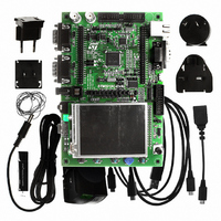
EVAL BOARD FOR STM32F107VCT
Manufacturer
STMicroelectronics
Type
MCUr
Datasheets
1.STM3210C-EVAL.pdf
(21 pages)
2.STM3210C-EVAL.pdf
(5 pages)
3.STM3210C-EVAL.pdf
(52 pages)
Specifications of STM3210C-EVAL
Contents
Fully Assembled Evaluation Board
Processor To Be Evaluated
STM32F107VCT
Processor Series
STM32
Interface Type
RS-232, USB, I2C, JTAG
Operating Supply Voltage
5 V
For Use With/related Products
STM32F107
Lead Free Status / RoHS Status
Lead free / RoHS Compliant
Other names
497-8924
Available stocks
Company
Part Number
Manufacturer
Quantity
Price
Company:

Part Number:
STM3210C-EVAL
Manufacturer:
STMicroelectronics
Quantity:
135
Company:
Part Number:
STM3210C-EVAL
Manufacturer:
STMicroelectronics
Quantity:
1


UM0600
2.1
Power supply
The STM3210C-EVAL evaluation board is designed to be powered by a 5 V DC power
supply and to be protected by PolyZen from a wrong power plug-in event.
It is possible to configure the evaluation board to use any of following three sources for the
power supply.
The power supply is configured by jumpers JP24 and JP25 as described in
Table 1.
To enable MCU power consumption measurement, JP1, JP14 and JP23 should be re-
configured as described in
JP25
JP24
Jumper
5 V DC power adapter connected to CN18, the power jack on the board (PSU on silk
screen for power supply unit).
5 V DC power with 500 mA limitation from CN2, the USB MicroAB connector (USB on
silkscreen).
5 V DC power from both CN8 and CN9, the extension connector for daughterboard
(DTB for daughterboard on silkscreen).
JP25 selects one of the three possible power supply resources.
For power supply jack (CN18) to the STM3210C-EVAL only, JP25 is set as
shown: (Default)
For power supply from the daughterboard connectors (CN8 and CN9) to
STM3210C-EVAL only, JP25 is set as shown:
For power supply from USB (CN2) to STM3210C-EVAL only, JP25 is set
as shown:
For power supply from power supply jack (CN18) to both STM3210C-
EVAL and daughterboard connected on CN8 and CN9, JP25 is set as
shown to the right (the daughterboard must not have its own power supply
connected):
V
V
bat
bat
Power related jumpers
is connected to 3.3 V power when JP24 is set as shown: (Default)
is connected to battery when JP24 is set as shown:
Table
Doc ID 15082 Rev 3
2.
Description
Hardware layout and configuration
Table
Configuration
1 2 3
1 2 3
1.
7/52
Related parts for STM3210C-EVAL
Image
Part Number
Description
Manufacturer
Datasheet
Request
R

Part Number:
Description:
DEV KIT FOR STM32
Manufacturer:
STMicroelectronics
Datasheet:

Part Number:
Description:
DEV KIT FOR STM32
Manufacturer:
STMicroelectronics
Datasheet:

Part Number:
Description:
DEV KIT FOR STM32
Manufacturer:
STMicroelectronics
Datasheet:

Part Number:
Description:
DEV KIT FOR STM32
Manufacturer:
STMicroelectronics
Datasheet:

Part Number:
Description:
MCU ARM 128KB FLASH MEM 64-LQFP
Manufacturer:
STMicroelectronics
Datasheet:

Part Number:
Description:
MCU ARM 32BIT 128KB FLASH 64BGA
Manufacturer:
STMicroelectronics
Datasheet:

Part Number:
Description:
MCU ARM 32BIT 256K FLASH 144LQFP
Manufacturer:
STMicroelectronics
Datasheet:

Part Number:
Description:
KIT STARTER FOR STM32F10X
Manufacturer:
STMicroelectronics
Datasheet:

Part Number:
Description:
MCU ARM 128K FLASH/TIMER
Manufacturer:
STMicroelectronics
Datasheet:

Part Number:
Description:
MCU ARM 128KB FLASH MEM 100-LQFP
Manufacturer:
STMicroelectronics
Datasheet:

Part Number:
Description:
MCU 32BIT ARM 64K FLASH 36VFQFPN
Manufacturer:
STMicroelectronics
Datasheet:
Part Number:
Description:
MCU ARM 32BIT 32KB FLASH 48LQFP
Manufacturer:
STMicroelectronics
Datasheet:
Part Number:
Description:
MCU ARM 32BIT 64KB FLASH 64LQFP
Manufacturer:
STMicroelectronics
Datasheet:
Part Number:
Description:
MCU ARM 32BIT 384KB FLASH 64LQFP
Manufacturer:
STMicroelectronics
Datasheet:

Part Number:
Description:
MCU 32BIT ARM 512K FLASH 100-LQF
Manufacturer:
STMicroelectronics
Datasheet: