STM3210C-EVAL STMicroelectronics, STM3210C-EVAL Datasheet - Page 12
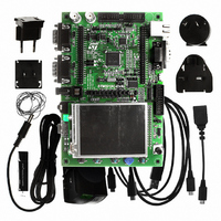
STM3210C-EVAL
Manufacturer Part Number
STM3210C-EVAL
Description
EVAL BOARD FOR STM32F107VCT
Manufacturer
STMicroelectronics
Type
MCUr
Datasheets
1.STM3210C-EVAL.pdf
(21 pages)
2.STM3210C-EVAL.pdf
(5 pages)
3.STM3210C-EVAL.pdf
(52 pages)
Specifications of STM3210C-EVAL
Contents
Fully Assembled Evaluation Board
Processor To Be Evaluated
STM32F107VCT
Processor Series
STM32
Interface Type
RS-232, USB, I2C, JTAG
Operating Supply Voltage
5 V
For Use With/related Products
STM32F107
Lead Free Status / RoHS Status
Lead free / RoHS Compliant
Other names
497-8924
Available stocks
Company
Part Number
Manufacturer
Quantity
Price
Company:

Part Number:
STM3210C-EVAL
Manufacturer:
STMicroelectronics
Quantity:
135
Company:
Part Number:
STM3210C-EVAL
Manufacturer:
STMicroelectronics
Quantity:
1


Hardware layout and configuration
2.9
12/52
Motor control
The STM3210C-EVAL evaluation board supports a three-phase brushless motor control via
a 34-pin connector CN17, which provides all required control and feedback signals to and
from a motor power-driving board.
Available signals on this connector include emergency stop, motor speed, 3 phase motor
current, bus voltage, heat sink temperature from the motor driving board and 6 channels of
PWM control signal going to the motor driving circuit.
JP 22 selects one of two kinds of synchronization methods for PFCs (power factor
correction).
The I/O pins used on the motor control connector CN17 are multiplexed with some
peripherals on the board; either motor control connector or multiplexed peripherals can be
enabled by setting jumpers JP10, JP21, JP22 and JP26.
Table 9.
JP22
JP21
JP10
JP26
Jumper
JP22 allows a PFC synchronization signal to be redirected to the timer 4 input capture 3
pin, additionally to the timer 4 external trigger input. Default setting: Not fitted.
JP21 should be kept open when encoder signal is input from pin31 of CN17 while it should
be kept on close when analog signal is from pin31 of CN17 for special motor.
Default setting: Not fitted.
MC_EnA is enabled when JP10 is set as shown:
PE0 is connected to SD card detection when JP26 is fitted.
JP26 should be kept open when PE0 is used as
MC_PFCsync2. Default setting: Fitted
I2S_MCK is enabled when JP10 is set as shown: (Default)
Motor control related jumpers
Doc ID 15082 Rev 3
Description
Configuration
1 2 3
1 2 3
Multiplexed
peripherals
MicroSD
Audio
UM0600
card
Related parts for STM3210C-EVAL
Image
Part Number
Description
Manufacturer
Datasheet
Request
R

Part Number:
Description:
DEV KIT FOR STM32
Manufacturer:
STMicroelectronics
Datasheet:

Part Number:
Description:
DEV KIT FOR STM32
Manufacturer:
STMicroelectronics
Datasheet:

Part Number:
Description:
DEV KIT FOR STM32
Manufacturer:
STMicroelectronics
Datasheet:

Part Number:
Description:
DEV KIT FOR STM32
Manufacturer:
STMicroelectronics
Datasheet:

Part Number:
Description:
MCU ARM 128KB FLASH MEM 64-LQFP
Manufacturer:
STMicroelectronics
Datasheet:

Part Number:
Description:
MCU ARM 32BIT 128KB FLASH 64BGA
Manufacturer:
STMicroelectronics
Datasheet:

Part Number:
Description:
MCU ARM 32BIT 256K FLASH 144LQFP
Manufacturer:
STMicroelectronics
Datasheet:

Part Number:
Description:
KIT STARTER FOR STM32F10X
Manufacturer:
STMicroelectronics
Datasheet:

Part Number:
Description:
MCU ARM 128K FLASH/TIMER
Manufacturer:
STMicroelectronics
Datasheet:

Part Number:
Description:
MCU ARM 128KB FLASH MEM 100-LQFP
Manufacturer:
STMicroelectronics
Datasheet:

Part Number:
Description:
MCU 32BIT ARM 64K FLASH 36VFQFPN
Manufacturer:
STMicroelectronics
Datasheet:
Part Number:
Description:
MCU ARM 32BIT 32KB FLASH 48LQFP
Manufacturer:
STMicroelectronics
Datasheet:
Part Number:
Description:
MCU ARM 32BIT 64KB FLASH 64LQFP
Manufacturer:
STMicroelectronics
Datasheet:
Part Number:
Description:
MCU ARM 32BIT 384KB FLASH 64LQFP
Manufacturer:
STMicroelectronics
Datasheet:

Part Number:
Description:
MCU 32BIT ARM 512K FLASH 100-LQF
Manufacturer:
STMicroelectronics
Datasheet: