STM3210C-EVAL STMicroelectronics, STM3210C-EVAL Datasheet - Page 14
STM3210C-EVAL
Manufacturer Part Number
STM3210C-EVAL
Description
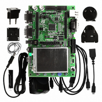
EVAL BOARD FOR STM32F107VCT
Manufacturer
STMicroelectronics
Type
MCUr
Datasheets
1.STM3210C-EVAL.pdf
(21 pages)
2.STM3210C-EVAL.pdf
(5 pages)
3.STM3210C-EVAL.pdf
(52 pages)
Specifications of STM3210C-EVAL
Contents
Fully Assembled Evaluation Board
Processor To Be Evaluated
STM32F107VCT
Processor Series
STM32
Interface Type
RS-232, USB, I2C, JTAG
Operating Supply Voltage
5 V
For Use With/related Products
STM32F107
Lead Free Status / RoHS Status
Lead free / RoHS Compliant
Other names
497-8924
Available stocks
Company
Part Number
Manufacturer
Quantity
Price
Company:

Part Number:
STM3210C-EVAL
Manufacturer:
STMicroelectronics
Quantity:
135
Company:
Part Number:
STM3210C-EVAL
Manufacturer:
STMicroelectronics
Quantity:
1


Hardware layout and configuration
2.11
2.12
14/52
MicroSD card
The 2 GByte (or more) microSD card connected to SPI3 of STM32F107VCT is available on
the board. MicroSD card detection is managed by the standard I/O port PE0.
JP15 must remain fitted to enable microSD card chip select.
Table 12.
Analog input
Two BNC connectors CN10 and CN11 are connected to PB0 and PA7 of the
STM32F107VCT as external analog input when a motor control connector is not used.
The 50 ohm terminal resister can be enabled by closing solder bridge SB3 and SB4 for each
BNC connector.
The test point TP7 and TP8 can be used for ADC precision measurement with BNC1
connector disconnected from PA7 by open SB5.
A low pass filter can be implemented for each BNC connector by replacing R141 and C64,
R143 and C65 with the value of resister and capacitor as requested by the end user’s
application.
There are also 3 analog signals available on the board:
1.
2.
3.
JP15
JP26
Jumper
10 Kohm potentiometer RV1 connected to PC4.
IDD measurement output signal connected to PA6 for power consumption test in RUN,
SLEEP and STOP mode.
Battery voltage measurement output signal connected to PC5. For battery voltage
measurement VBAT is connected to ADC input using resistor divider since this voltage
may be higher than MCU_VDD when the battery is new. The resistor divider 2/3 needs
to be pulled low by an I/O expander (VBAT_DIV on EXP_IO12) in order to avoid
permanent current on this bridge.
JP15 enables microSD card chip select line. MicroSD card chip select is enabled when
JP15 is fitted.
JP15 should be kept open when PA4 is configured as a DAC output for audio DAC.
Default setting: Fitted.
PE0 is connected to SD card detection when JP26 is fitted. JP26 should be kept on open
when PE0 is used as MC_PFCsync2.
Default setting: Fitted.
MicroSD card related jumper
Doc ID 15082 Rev 3
Description
UM0600
Related parts for STM3210C-EVAL
Image
Part Number
Description
Manufacturer
Datasheet
Request
R

Part Number:
Description:
DEV KIT FOR STM32
Manufacturer:
STMicroelectronics
Datasheet:

Part Number:
Description:
DEV KIT FOR STM32
Manufacturer:
STMicroelectronics
Datasheet:

Part Number:
Description:
DEV KIT FOR STM32
Manufacturer:
STMicroelectronics
Datasheet:

Part Number:
Description:
DEV KIT FOR STM32
Manufacturer:
STMicroelectronics
Datasheet:

Part Number:
Description:
MCU ARM 128KB FLASH MEM 64-LQFP
Manufacturer:
STMicroelectronics
Datasheet:

Part Number:
Description:
MCU ARM 32BIT 128KB FLASH 64BGA
Manufacturer:
STMicroelectronics
Datasheet:

Part Number:
Description:
MCU ARM 32BIT 256K FLASH 144LQFP
Manufacturer:
STMicroelectronics
Datasheet:

Part Number:
Description:
KIT STARTER FOR STM32F10X
Manufacturer:
STMicroelectronics
Datasheet:

Part Number:
Description:
MCU ARM 128K FLASH/TIMER
Manufacturer:
STMicroelectronics
Datasheet:

Part Number:
Description:
MCU ARM 128KB FLASH MEM 100-LQFP
Manufacturer:
STMicroelectronics
Datasheet:

Part Number:
Description:
MCU 32BIT ARM 64K FLASH 36VFQFPN
Manufacturer:
STMicroelectronics
Datasheet:
Part Number:
Description:
MCU ARM 32BIT 32KB FLASH 48LQFP
Manufacturer:
STMicroelectronics
Datasheet:
Part Number:
Description:
MCU ARM 32BIT 64KB FLASH 64LQFP
Manufacturer:
STMicroelectronics
Datasheet:
Part Number:
Description:
MCU ARM 32BIT 384KB FLASH 64LQFP
Manufacturer:
STMicroelectronics
Datasheet:

Part Number:
Description:
MCU 32BIT ARM 512K FLASH 100-LQF
Manufacturer:
STMicroelectronics
Datasheet: