DEMO9S08EL32 Freescale Semiconductor, DEMO9S08EL32 Datasheet - Page 162
DEMO9S08EL32
Manufacturer Part Number
DEMO9S08EL32
Description
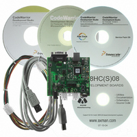
BOARD DEMO FOR 9S08 EL MCU
Manufacturer
Freescale Semiconductor
Type
MCUr
Datasheets
1.DEMO9S08EL32.pdf
(356 pages)
2.DEMO9S08EL32.pdf
(14 pages)
3.DEMO9S08EL32.pdf
(2 pages)
Specifications of DEMO9S08EL32
Contents
Evaluation Board
Processor To Be Evaluated
MC9S08EL32
Data Bus Width
8 bit
Interface Type
RS-232, USB
Operating Supply Voltage
12 V
Silicon Manufacturer
Freescale
Core Architecture
HCS08
Core Sub-architecture
HCS08
Silicon Core Number
MC9S08
Silicon Family Name
S08EL
Rohs Compliant
Yes
For Use With/related Products
MC9S08EL32
Lead Free Status / RoHS Status
Lead free / RoHS Compliant


Analog-to-Digital Converter (S08ADC10V1)
10.6.2.4
The ADC quantizes the ideal straight-line transfer function into 1024 steps (in 10-bit mode). Each step
ideally has the same height (1 code) and width. The width is defined as the delta between the transition
points to one code and the next. The ideal code width for an N bit converter (in this case N can be 8 or 10),
defined as 1
There is an inherent quantization error due to the digitization of the result. For 8-bit or 10-bit conversions
the code will transition when the voltage is at the midpoint between the points where the straight line
transfer function is exactly represented by the actual transfer function. Therefore, the quantization error
will be ± 1/2
conversion is only 1/2
10.6.2.5
The ADC may also exhibit non-linearity of several forms. Every effort has been made to reduce these
errors but the system should be aware of them because they affect overall accuracy. These errors are:
10.6.2.6
Analog-to-digital converters are susceptible to three special forms of error. These are code jitter,
non-monotonicity, and missing codes.
Code jitter is when, at certain points, a given input voltage converts to one of two values when sampled
repeatedly. Ideally, when the input voltage is infinitesimally smaller than the transition voltage, the
162
•
•
•
•
•
•
•
Average the result by converting the analog input many times in succession and dividing the sum
of the results. Four samples are required to eliminate the effect of a 1
Reduce the effect of synchronous noise by operating off the asynchronous clock (ADACK) and
averaging. Noise that is synchronous to ADCK cannot be averaged out.
Zero-scale error (E
the actual code width of the first conversion and the ideal code width (1/2
conversion is $001, then the difference between the actual $001 code width and its ideal (1
used.
Full-scale error (E
the last conversion and the ideal code width (1.5
difference between the actual $3FE code width and its ideal (1
Differential non-linearity (DNL) — This error is defined as the worst-case difference between the
actual code width and the ideal code width for all conversions.
Integral non-linearity (INL) — This error is defined as the highest-value the (absolute value of the)
running sum of DNL achieves. More simply, this is the worst-case difference of the actual
transition voltage to a given code and its corresponding ideal transition voltage, for all codes.
Total unadjusted error (TUE) — This error is defined as the difference between the actual transfer
function and the ideal straight-line transfer function, and therefore includes all forms of error.
LSB
LSB
Code Width and Quantization Error
Linearity Errors
Code Jitter, Non-Monotonicity and Missing Codes
, is:
in 8- or 10-bit mode. As a consequence, however, the code width of the first ($000)
LSB
MC9S08EL32 Series and MC9S08SL16 Series Data Sheet, Rev. 3
FS
ZS
and the code width of the last ($FF or $3FF) is 1.5
) — This error is defined as the difference between the actual code width of
) (sometimes called offset) — This error is defined as the difference between
1
LSB
= (V
REFH
- V
REFL
LSB
) / 2
). Note, if the last conversion is $3FE, then the
N
LSB
) is used.
LSB
LSB
, one-time error.
.
LSB
Freescale Semiconductor
). Note, if the first
Eqn. 10-2
LSB
) is
Related parts for DEMO9S08EL32
Image
Part Number
Description
Manufacturer
Datasheet
Request
R

Part Number:
Description:
Manufacturer:
Freescale Semiconductor, Inc
Datasheet:
Part Number:
Description:
Manufacturer:
Freescale Semiconductor, Inc
Datasheet:
Part Number:
Description:
Manufacturer:
Freescale Semiconductor, Inc
Datasheet:
Part Number:
Description:
Manufacturer:
Freescale Semiconductor, Inc
Datasheet:
Part Number:
Description:
Manufacturer:
Freescale Semiconductor, Inc
Datasheet:
Part Number:
Description:
Manufacturer:
Freescale Semiconductor, Inc
Datasheet:
Part Number:
Description:
Manufacturer:
Freescale Semiconductor, Inc
Datasheet:
Part Number:
Description:
Manufacturer:
Freescale Semiconductor, Inc
Datasheet:
Part Number:
Description:
Manufacturer:
Freescale Semiconductor, Inc
Datasheet:
Part Number:
Description:
Manufacturer:
Freescale Semiconductor, Inc
Datasheet:
Part Number:
Description:
Manufacturer:
Freescale Semiconductor, Inc
Datasheet:
Part Number:
Description:
Manufacturer:
Freescale Semiconductor, Inc
Datasheet:
Part Number:
Description:
Manufacturer:
Freescale Semiconductor, Inc
Datasheet:
Part Number:
Description:
Manufacturer:
Freescale Semiconductor, Inc
Datasheet:
Part Number:
Description:
Manufacturer:
Freescale Semiconductor, Inc
Datasheet: