DEMO9S08EL32 Freescale Semiconductor, DEMO9S08EL32 Datasheet - Page 190
DEMO9S08EL32
Manufacturer Part Number
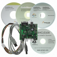
DEMO9S08EL32
Description
BOARD DEMO FOR 9S08 EL MCU
Manufacturer
Freescale Semiconductor
Type
MCUr
Datasheets
1.DEMO9S08EL32.pdf
(356 pages)
2.DEMO9S08EL32.pdf
(14 pages)
3.DEMO9S08EL32.pdf
(2 pages)
Specifications of DEMO9S08EL32
Contents
Evaluation Board
Processor To Be Evaluated
MC9S08EL32
Data Bus Width
8 bit
Interface Type
RS-232, USB
Operating Supply Voltage
12 V
Silicon Manufacturer
Freescale
Core Architecture
HCS08
Core Sub-architecture
HCS08
Silicon Core Number
MC9S08
Silicon Family Name
S08EL
Rohs Compliant
Yes
For Use With/related Products
MC9S08EL32
Lead Free Status / RoHS Status
Lead free / RoHS Compliant


192
INITREQ
WAKETX
BEDD
Field
5
4
3
Reset
W
R
Initialization Request — Requesting initialization mode by setting this bit will place the SLIC module into its
initialized state immediately. As a result of setting INITREQ, INITACK will be set in SLCS. INITACK = 1 causes
all SLIC register bits (except SLCWCM: write once) to be held in their reset states and become not writable until
INITACK has been cleared. If transmission or reception of data is in progress, the transaction will be terminated
immediately upon entry into initialization mode (signified by INITACK being set to 1). To return to normal SLIC
operation after the SLIC has been initialized (the INITACK is high), the INITREQ must be cleared by software.
0 Normal operation
1 Request for SLIC to be put into reset state immediately
BEDD Bit Error Detection Disable — This bit allows the user to disable bit error detection circuitry. Bit error
detection monitors the received bits to determine if they match the state of the corresponding transmitted bits.
When bit error detection is enabled and a mismatch between transmitted bit and received bit is detected, a bit
error is reported to the user through the SLCSV register and a SLIC interrupt is generated (if SLIC interrupts are
enabled). The user must ensure that all physical delays which affect the timing of received bits are not
significant enough to cause the bit error detection circuitry to incorrectly detect bit errors at higher LIN
bus speeds. See
0 Bit Error Detection Enabled
1 Bit Error Detection Disabled no bit errors will be detected or reported
Transmit Wakeup Symbol— This bit allows the user to transmit a wakeup symbol on the LIN bus. When set,
this sends a wakeup symbol, as defined in the LIN specification a single time, then resets to 0. This bit will read
1 while the wakeup symbol is being transmitted on the bus. This bit will be automatically cleared when the wakeup
symbol is complete.
0 Normal operation
1 Send wakeup symbol on LIN bus
0
0
7
= Unimplemented or Reserved
MC9S08EL32 Series and MC9S08SL16 Series Data Sheet, Rev. 3
Section 12.6.15, “Bit Error Detection and Physical Layer
Bit Error detection is not recommended for use in BTM mode,
as bit errors are reported on bit boundaries, not byte
boundaries. This can result in misaligned data.
Bit errors must not be disabled during normal LIN operations,
as it allows the SLIC module to operate outside of the LIN
specification. If you switch off bit error detection, there is no
guaranteed way to detect bus collisions and automatically
cease transmissions. Therefore pending SLIC transmissions
may continue after a bit error should have been detected,
potentially corrupting bus traffic.
6
0
0
Figure 12-4. SLIC Control Register 1 (SLCC1)
Table 12-1. SLCC1 Field Descriptions
INITREQ
1
5
BEDD
4
0
Description
NOTE
WAKETX
0
3
TXABRT
Delay,” for details.
2
0
Freescale Semiconductor
IMSG
0
1
SLCIE
0
0
Related parts for DEMO9S08EL32
Image
Part Number
Description
Manufacturer
Datasheet
Request
R

Part Number:
Description:
Manufacturer:
Freescale Semiconductor, Inc
Datasheet:
Part Number:
Description:
Manufacturer:
Freescale Semiconductor, Inc
Datasheet:
Part Number:
Description:
Manufacturer:
Freescale Semiconductor, Inc
Datasheet:
Part Number:
Description:
Manufacturer:
Freescale Semiconductor, Inc
Datasheet:
Part Number:
Description:
Manufacturer:
Freescale Semiconductor, Inc
Datasheet:
Part Number:
Description:
Manufacturer:
Freescale Semiconductor, Inc
Datasheet:
Part Number:
Description:
Manufacturer:
Freescale Semiconductor, Inc
Datasheet:
Part Number:
Description:
Manufacturer:
Freescale Semiconductor, Inc
Datasheet:
Part Number:
Description:
Manufacturer:
Freescale Semiconductor, Inc
Datasheet:
Part Number:
Description:
Manufacturer:
Freescale Semiconductor, Inc
Datasheet:
Part Number:
Description:
Manufacturer:
Freescale Semiconductor, Inc
Datasheet:
Part Number:
Description:
Manufacturer:
Freescale Semiconductor, Inc
Datasheet:
Part Number:
Description:
Manufacturer:
Freescale Semiconductor, Inc
Datasheet:
Part Number:
Description:
Manufacturer:
Freescale Semiconductor, Inc
Datasheet:
Part Number:
Description:
Manufacturer:
Freescale Semiconductor, Inc
Datasheet: