DEMO9S08EL32 Freescale Semiconductor, DEMO9S08EL32 Datasheet - Page 195
DEMO9S08EL32
Manufacturer Part Number
DEMO9S08EL32
Description
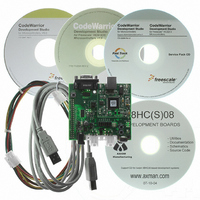
BOARD DEMO FOR 9S08 EL MCU
Manufacturer
Freescale Semiconductor
Type
MCUr
Datasheets
1.DEMO9S08EL32.pdf
(356 pages)
2.DEMO9S08EL32.pdf
(14 pages)
3.DEMO9S08EL32.pdf
(2 pages)
Specifications of DEMO9S08EL32
Contents
Evaluation Board
Processor To Be Evaluated
MC9S08EL32
Data Bus Width
8 bit
Interface Type
RS-232, USB
Operating Supply Voltage
12 V
Silicon Manufacturer
Freescale
Core Architecture
HCS08
Core Sub-architecture
HCS08
Silicon Core Number
MC9S08
Silicon Family Name
S08EL
Rohs Compliant
Yes
For Use With/related Products
MC9S08EL32
Lead Free Status / RoHS Status
Lead free / RoHS Compliant


1
12.3.5
SLIC state vector register (SLCSV) is provided to substantially decrease the CPU overhead associated
with servicing interrupts while under operation of a LIN protocol. It provides an index offset that is directly
related to the LIN module’s current state, which can be used with a user supplied jump table to rapidly
enter an interrupt service routine. This eliminates the need for the user to maintain a duplicate state
machine in software.
Freescale Semiconductor
SLCACT
SLCACT may not be clear during all idle times of the bus. For example, if IMSG was used to ignore the data interrupts of an
extended message frame, SLCACT will remain set until another LIN message is received and either the RX Message Buffer
Full Checksum OK (SLCSV = 0x10) or the TX Message Buffer Empty Checksum Transmitted (SLCSV = 0x08) interrupt
sources are asserted and cleared. When clear, SLCACT always indicates times when the SLIC module is not active, but it is
possible for the SLIC module to be not active with SLCACT set. SLCACT has no meaning in BTM mode.
INITACK
SLCF
Field
7
5
0
Reset
1
W
R
SLIC State Vector Register (SLCSV)
SLIC Active (Oscillator Trim Blocking Semaphore) — SLCACT is used to indicate if it is safe to trim the
oscillator based upon current SLIC activity in LIN mode. This bit indicates that the SLIC module might be currently
receiving a message header, synchronization byte, ID byte, or sending or receiving data bytes. This bit is
read-only. This bit has no meaning in BTM mode (BTM =1).
0 SLIC module not active (safe to trim oscillator) SLCACT is cleared by the SLIC module only upon assertion of
1 SLIC module activity (not safe to trim oscillator)
Initialization Mode Acknowledge — INITACK indicates whether the SLIC module is in the reset mode as a
result of writing INITREQ in SLCC1. INITACK = 1 causes all SLIC register bits (except SLCWCM: write once) to
be held in their reset state and become not writable until INITACK has been cleared. Clear INITACK by clearing
INITREQ in SLCC1. After INITACK is cleared, the SLIC module proceeds to SLIC DISABLED mode (see
Figure
operating mode. INITACK is a read-only bit.
0 Normal operation
1 SLIC module is in reset state
SLIC Interrupt Flag — The SLCF interrupt flag indicates if a SLIC module interrupt is pending. If set, the SLCSV
is then used to determine what interrupt is pending. This flag is cleared by writing a 1 to the bit. If additional
interrupt sources are pending, the bit will be automatically set to 1 again by the SLIC.
0 No SLIC interrupt pending
1 SLIC interrupt pending
SLCACT
the RX Message Buffer Full Checksum OK (SLCSV = 0x10) or the TX Message Buffer Empty Checksum
Transmitted (SLCSV = 0x08) interrupt sources.
SLCACT is automatically set to 1 if a falling edge is seen on the SLCRX pin and has successfully been passed
through the digital RX filter. This edge is the potential beginning of a LIN message frame.
0
7
12-2) in which the other SLIC register bits are writable and can be configured to the desired SLIC
= Unimplemented or Reserved
MC9S08EL32 Series and MC9S08SL16 Series Data Sheet, Rev. 3
6
0
0
Figure 12-8. SLIC Status Register (SLCS)
Table 12-6. SLCS Field Descriptions
INITACK
1
5
4
0
0
Description
0
0
3
2
0
0
0
0
1
SLCF
0
0
197
Related parts for DEMO9S08EL32
Image
Part Number
Description
Manufacturer
Datasheet
Request
R

Part Number:
Description:
Manufacturer:
Freescale Semiconductor, Inc
Datasheet:
Part Number:
Description:
Manufacturer:
Freescale Semiconductor, Inc
Datasheet:
Part Number:
Description:
Manufacturer:
Freescale Semiconductor, Inc
Datasheet:
Part Number:
Description:
Manufacturer:
Freescale Semiconductor, Inc
Datasheet:
Part Number:
Description:
Manufacturer:
Freescale Semiconductor, Inc
Datasheet:
Part Number:
Description:
Manufacturer:
Freescale Semiconductor, Inc
Datasheet:
Part Number:
Description:
Manufacturer:
Freescale Semiconductor, Inc
Datasheet:
Part Number:
Description:
Manufacturer:
Freescale Semiconductor, Inc
Datasheet:
Part Number:
Description:
Manufacturer:
Freescale Semiconductor, Inc
Datasheet:
Part Number:
Description:
Manufacturer:
Freescale Semiconductor, Inc
Datasheet:
Part Number:
Description:
Manufacturer:
Freescale Semiconductor, Inc
Datasheet:
Part Number:
Description:
Manufacturer:
Freescale Semiconductor, Inc
Datasheet:
Part Number:
Description:
Manufacturer:
Freescale Semiconductor, Inc
Datasheet:
Part Number:
Description:
Manufacturer:
Freescale Semiconductor, Inc
Datasheet:
Part Number:
Description:
Manufacturer:
Freescale Semiconductor, Inc
Datasheet: