DEMO9S08EL32 Freescale Semiconductor, DEMO9S08EL32 Datasheet - Page 204
DEMO9S08EL32
Manufacturer Part Number
DEMO9S08EL32
Description
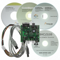
BOARD DEMO FOR 9S08 EL MCU
Manufacturer
Freescale Semiconductor
Type
MCUr
Datasheets
1.DEMO9S08EL32.pdf
(356 pages)
2.DEMO9S08EL32.pdf
(14 pages)
3.DEMO9S08EL32.pdf
(2 pages)
Specifications of DEMO9S08EL32
Contents
Evaluation Board
Processor To Be Evaluated
MC9S08EL32
Data Bus Width
8 bit
Interface Type
RS-232, USB
Operating Supply Voltage
12 V
Silicon Manufacturer
Freescale
Core Architecture
HCS08
Core Sub-architecture
HCS08
Silicon Core Number
MC9S08
Silicon Family Name
S08EL
Rohs Compliant
Yes
For Use With/related Products
MC9S08EL32
Lead Free Status / RoHS Status
Lead free / RoHS Compliant


12.6.3
The checksum field is a data integrity measure for LIN message frames, used to signal errors in data
consistency. The LIN 1.3 checksum calculation only covers the data field, but the SLIC module also
supports an enhanced checksum calculation which also includes the identifier field. For more information
on the checksum calculation, refer to
12.6.4
In designing a practical module, certain reasonable constraints must be placed on the LIN message traffic
which are not necessarily explicitly specified in the LIN specification. The SLIC module presumes that:
12.6.5
Each change of state of the SLIC module is encoded in the SLIC state vector register (SLCSV). This is an
efficient method of handling state changes, indicating to the user not only the current status of the SLIC
module, but each state change will also generate an interrupt (if SLIC interrupts are enabled). For more
detailed information on the SLCSV, please refer to
In the software diagrams in the following subsections, when an interrupt is shown, the first step must
always be reading SLCSV to determine what is the current status of the SLIC module. Likewise, when the
diagrams indicate to “EXIT ISR”, the final step to exiting the interrupt service routine is to clear the SLCF
interrupt flag. This can only be done if the SLCSV has first been read, and in the case that data has been
received (such as an ID byte or command message data) the SLCD has been read at least one time.
After SLCSV is read, it will switch to the next pending state, so the user must be sure it is copied only once
into a software variable at the beginning of the interrupt service routine to avoid inadvertently clearing a
pending interrupt source. Additional decisions based on this value must be made from the software
variable, rather than from the SLCSV itself.
After exiting the ISR, normal application code may resume. If the diagram indicates to “RETURN TO
IDLE,” it indicates that all processing for the current message frame has been completed. If an error was
detected and the corresponding error code loaded into the SLCSV, any pending data in the data buffer will
be flushed out and the SLIC returned to its idle state, seeking out the next message frame header.
12.6.6
12.6.6.1
The SLIC module does not require very much initialization, due to its self-synchronizing design. Because
no prior knowledge of the bit rate is required to synchronize to the LIN bus, no programming of bit rate is
required.
At initialization time, the user must configure:
206
•
•
•
Timeout for no-bus-activity = 1 second.
SLIC prescale register (SLIC digital receive filter adjustment).
Wait clock mode operation.
LIN Checksum Field
SLIC Module Constraints
SLCSV Interrupt Handling
SLIC Module Initialization Procedure
LIN Mode Initialization
MC9S08EL32 Series and MC9S08SL16 Series Data Sheet, Rev. 3
Section 12.6.13, “LIN Data Integrity Checking
Section 12.3.5, “SLIC State Vector Register
Freescale Semiconductor
Methods.”
(SLCSV).”
Related parts for DEMO9S08EL32
Image
Part Number
Description
Manufacturer
Datasheet
Request
R

Part Number:
Description:
Manufacturer:
Freescale Semiconductor, Inc
Datasheet:
Part Number:
Description:
Manufacturer:
Freescale Semiconductor, Inc
Datasheet:
Part Number:
Description:
Manufacturer:
Freescale Semiconductor, Inc
Datasheet:
Part Number:
Description:
Manufacturer:
Freescale Semiconductor, Inc
Datasheet:
Part Number:
Description:
Manufacturer:
Freescale Semiconductor, Inc
Datasheet:
Part Number:
Description:
Manufacturer:
Freescale Semiconductor, Inc
Datasheet:
Part Number:
Description:
Manufacturer:
Freescale Semiconductor, Inc
Datasheet:
Part Number:
Description:
Manufacturer:
Freescale Semiconductor, Inc
Datasheet:
Part Number:
Description:
Manufacturer:
Freescale Semiconductor, Inc
Datasheet:
Part Number:
Description:
Manufacturer:
Freescale Semiconductor, Inc
Datasheet:
Part Number:
Description:
Manufacturer:
Freescale Semiconductor, Inc
Datasheet:
Part Number:
Description:
Manufacturer:
Freescale Semiconductor, Inc
Datasheet:
Part Number:
Description:
Manufacturer:
Freescale Semiconductor, Inc
Datasheet:
Part Number:
Description:
Manufacturer:
Freescale Semiconductor, Inc
Datasheet:
Part Number:
Description:
Manufacturer:
Freescale Semiconductor, Inc
Datasheet: