DEMO9S08EL32 Freescale Semiconductor, DEMO9S08EL32 Datasheet - Page 222
DEMO9S08EL32
Manufacturer Part Number
DEMO9S08EL32
Description
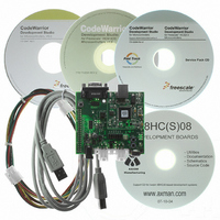
BOARD DEMO FOR 9S08 EL MCU
Manufacturer
Freescale Semiconductor
Type
MCUr
Datasheets
1.DEMO9S08EL32.pdf
(356 pages)
2.DEMO9S08EL32.pdf
(14 pages)
3.DEMO9S08EL32.pdf
(2 pages)
Specifications of DEMO9S08EL32
Contents
Evaluation Board
Processor To Be Evaluated
MC9S08EL32
Data Bus Width
8 bit
Interface Type
RS-232, USB
Operating Supply Voltage
12 V
Silicon Manufacturer
Freescale
Core Architecture
HCS08
Core Sub-architecture
HCS08
Silicon Core Number
MC9S08
Silicon Family Name
S08EL
Rohs Compliant
Yes
For Use With/related Products
MC9S08EL32
Lead Free Status / RoHS Status
Lead free / RoHS Compliant


12.6.16 Byte Transfer Mode Operation
This subsection describes the operation and limitations of the optional UART-like byte transfer mode
(BTM). This mode allows sending and receiving individual bytes, but changes the behavior of the SLCBT
registers (now read/write registers) and locks the SLCDLC to 1 byte data length. The SLCBT value now
becomes the bit time reference for the SLIC, where the software sets the length of one bit time rather than
the SLIC module itself. This is similar to an input capture/output compare (IC/OC) count in a timer
module, where the count value represents the number of SLIC clock counts in one bit time.
Byte transfer mode assumes that the user has a very stable, precise oscillator, resonator, or clock reference
input into the MCU and is therefore not appropriate for use with internal oscillators. There is no
synchronization method available to the user in this mode and the user must tell the SLIC how many clock
counts comprise a bit time.
to determine the SLCBT value for different settings.
In the example in
automatically revert to 0x14, resulting in transmitted bit times that are 1.33 SLIC clock periods too short
rather than 0.667 SLIC clock periods too long. The optimal choice, which gives the smallest resolution
error, is the closest even number of SLIC clocks to the exact calculated SLCBT value.
There is a trade-off between maximum bit rate and resolution with the SLIC in BTM mode. Faster SLIC
clock speeds improve resolution, but require higher numbers to be written to the SLCBT registers for a
given desired bit rate. It is up to the user to determine what level of resolution is acceptable for the given
application.
224
It is possible to use the LIN autobauding circuitry in a non-LIN system to
derive the correct bit timing values if system constraints allow. To do this
the SLIC module must be activated in LIN mode (BTM=0) and receive a
break symbol, 0x55 data byte and one additional data byte (at the desired
BTM speed). Upon receiving this sequence of symbols which appears to be
a LIN header, the SLIC module will assert an ID received successfully
interrupt (SLCSV=0x2C). The value in the SLCBT registers will reflect the
bit rate which the 0x55 data character was received and can be saved to
RAM. The user then switches the SLIC into BTM mode and reloads this
value from RAM and the SLIC will be configured to communicate in BTM
mode at the baud rate which the 0x55 data character was sent. Care must be
taken to ensure that any change between LIN and BTM modes be done at
known states in message traffic, such as between message frames, after an
ID is successfully received in LIN mode, or when the LIN bus is IDLE as
indicated by the SLCACT bit equal to 0.
Do not set the SLCBT registers to a value lower than 16 clock counts for
correct operation.
Figure
MC9S08EL32 Series and MC9S08SL16 Series Data Sheet, Rev. 3
12-17, the user should write 0x16, as a write of 0x15 (decimal value of 21) would
Figure
12-17,
Figure
12-18,
NOTE
NOTE
Figure
12-19, and
Figure 12-20
Freescale Semiconductor
show calculations
Related parts for DEMO9S08EL32
Image
Part Number
Description
Manufacturer
Datasheet
Request
R

Part Number:
Description:
Manufacturer:
Freescale Semiconductor, Inc
Datasheet:
Part Number:
Description:
Manufacturer:
Freescale Semiconductor, Inc
Datasheet:
Part Number:
Description:
Manufacturer:
Freescale Semiconductor, Inc
Datasheet:
Part Number:
Description:
Manufacturer:
Freescale Semiconductor, Inc
Datasheet:
Part Number:
Description:
Manufacturer:
Freescale Semiconductor, Inc
Datasheet:
Part Number:
Description:
Manufacturer:
Freescale Semiconductor, Inc
Datasheet:
Part Number:
Description:
Manufacturer:
Freescale Semiconductor, Inc
Datasheet:
Part Number:
Description:
Manufacturer:
Freescale Semiconductor, Inc
Datasheet:
Part Number:
Description:
Manufacturer:
Freescale Semiconductor, Inc
Datasheet:
Part Number:
Description:
Manufacturer:
Freescale Semiconductor, Inc
Datasheet:
Part Number:
Description:
Manufacturer:
Freescale Semiconductor, Inc
Datasheet:
Part Number:
Description:
Manufacturer:
Freescale Semiconductor, Inc
Datasheet:
Part Number:
Description:
Manufacturer:
Freescale Semiconductor, Inc
Datasheet:
Part Number:
Description:
Manufacturer:
Freescale Semiconductor, Inc
Datasheet:
Part Number:
Description:
Manufacturer:
Freescale Semiconductor, Inc
Datasheet: