BMSKTOPASA900(DCE) Toshiba, BMSKTOPASA900(DCE) Datasheet - Page 957
BMSKTOPASA900(DCE)
Manufacturer Part Number
BMSKTOPASA900(DCE)
Description
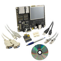
KIT STARTER TMPA900 USB JTAG
Manufacturer
Toshiba
Series
TOPASr
Type
MCUr
Specifications of BMSKTOPASA900(DCE)
Contents
Evaluation Board, Cable(s), Software and Documentation
For Use With/related Products
TMPA900CMXBG
Lead Free Status / RoHS Status
Lead free / RoHS Compliant


4.6
TMPA900CMXBG
TMPA900CMXBG
MCU
Recommended Oscillation Circuit
information when selecting the resonator to be used.
The TMPA900CM is evaluated by using the resonators shown below. Please use this
MCU
Note: The total load capacitance of the oscillation pins is the sum of the external (or internal) load capacitances
Note 1: Constants C1 and C2 indicates values for the built-in load capacitance type.
Note 2: The part numbers and specifications of Kyocera’s products are updated as occasion requires. For details,
Note 3: When the ceramic resonator is used for high-frequency oscillator circuit, USB device and host controller
Note: The part numbers and specifications of KYOCERA KINSEKI’s products are updated as occasion requires. For
(1) Connection example
(2) Recommended ceramic resonator: KYOCERA KINSEKI Corporation
(3) Recommended crystal low-frequency resonator: KYOCERA KINSEKI Corporation
C1and C2 and the stray capacitance on the circuit board. Even if the recommended C1 and C2 constants are
used, the total load capacitance may vary with each board. In board design, the patterns around the oscillation
circuit must be as short as possible. We also recommend that oscillation evaluations be performed on the
actual board to be used.
please check the website of Murata.
http://global.kyocera.com/
requires using the clock in high precision. In this case, the clock of X1USB pin should be used the clock
precision is 24MHz ±100ppm.
details, please check the website of KYOCERA KINSEKI.
http://global.kyocera.com/
Oscillation
frequency
The table below shows the recommended circuit constants of the low-frequency
oscillation circuit.
The table below shows the recommended circuit constants for the high-frequency
oscillation circuit.
27.000
24.000
C1
high-frequency oscillator
[MHZ]
Connection diagram of
Oscillation
frequency
X1
32.768
[kHz]
Type
SMD CX2520SB27000B0HLQZ1
SMD CX2520SB24000C0HLQZ1
Rf
C2
Recommended
Recommended resonator
ST3215SB
X2
resonator
Rd
TMPA900CM- 956
TENTATIVE
C1
low-frequency oscillator
Connection diagram of
XT1
[pF]
Recommended constants
C1
7
Rf
Recommended constants
[pF]
[pF]
C1
C2
6
7
7
C2
[pF]
XT2
C2
820 Built-In
6
7
Rd
[Ω]
Rd
[Ω]
Rd
0
[Ω]
Rf
[Ω]
voltage range [V]
Rf
0
Power supply
3.0 to 3.6
Recommended operating
voltage range [V]
Power supply
Recommended operating
1.4 to 1.6
conditions
conditions
Temperature
range [°C]
-20 to 85
Temperature
TMPA900CM
range [°C]
-20 to 85
2009-10-14
Related parts for BMSKTOPASA900(DCE)
Image
Part Number
Description
Manufacturer
Datasheet
Request
R

Part Number:
Description:
Toshiba Semiconductor [TOSHIBA IGBT Module Silicon N Channel IGBT]
Manufacturer:
TOSHIBA Semiconductor CORPORATION
Datasheet:
Part Number:
Description:
TOSHIBA GTR MODULE SILICON NPN TRIPLE DIFFUSED TYPE
Manufacturer:
TOSHIBA Semiconductor CORPORATION
Datasheet:
Part Number:
Description:
TOSHIBA GTR Module Silicon N Channel IGBT
Manufacturer:
TOSHIBA Semiconductor CORPORATION
Datasheet:
Part Number:
Description:
TOSHIBA Intelligent Power Module Silicon N Channel IGBT
Manufacturer:
TOSHIBA Semiconductor CORPORATION
Datasheet:
Part Number:
Description:
TOSHIBA INTELLIGENT POWER MODULE SILICON N CHANNEL LGBT
Manufacturer:
TOSHIBA Semiconductor CORPORATION
Datasheet:
Part Number:
Description:
TOSHIBA IGBT Module Silicon N Channel IGBT
Manufacturer:
TOSHIBA Semiconductor CORPORATION
Datasheet:
Part Number:
Description:
TOSHIBA GTR MODULE SILICON N−CHANNEL IGBT
Manufacturer:
TOSHIBA Semiconductor CORPORATION
Datasheet:
Part Number:
Description:
TOSHIBA Intelligent Power Module Silicon N Channel IGBT
Manufacturer:
TOSHIBA Semiconductor CORPORATION
Datasheet:
Part Number:
Description:
TOSHIBA GTR Module Silicon N Channel IGBT
Manufacturer:
TOSHIBA Semiconductor CORPORATION
Datasheet:
Part Number:
Description:
TOSHIBA INTELLIGENT POWER MODULE
Manufacturer:
TOSHIBA Semiconductor CORPORATION
Datasheet:
Part Number:
Description:
TOSHIBA Intelligent Power Module Silicon N Channel IGBT
Manufacturer:
TOSHIBA Semiconductor CORPORATION
Datasheet:
Part Number:
Description:
TOSHIBA Intelligent Power Module Silicon N Channel IGBT
Manufacturer:
TOSHIBA Semiconductor CORPORATION
Datasheet:
Part Number:
Description:
TOSHIBA IGBT Module Silicon N Channel IGBT
Manufacturer:
TOSHIBA Semiconductor CORPORATION
Datasheet:
Part Number:
Description:
TOSHIBA Intelligent Power Module Silicon N Channel IGBT
Manufacturer:
TOSHIBA Semiconductor CORPORATION
Datasheet:
Part Number:
Description:
Toshiba Semiconductor [SILICON N CHANNEL 1GBT]
Manufacturer:
TOSHIBA Semiconductor CORPORATION
Datasheet: