HW-V5-ML501-UNI-G Xilinx Inc, HW-V5-ML501-UNI-G Datasheet - Page 32
HW-V5-ML501-UNI-G
Manufacturer Part Number
HW-V5-ML501-UNI-G
Description
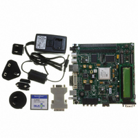
EVALUATION PLATFORM VIRTEX-5
Manufacturer
Xilinx Inc
Series
Virtex™-5 LXr
Type
FPGAr
Datasheet
1.HW-V5-ML501-UNI-G.pdf
(42 pages)
Specifications of HW-V5-ML501-UNI-G
Design Resources
ML501 Ref Design User Guide ML501 Schematics
Contents
ML501 Platform, DVI Adapter and CompactFlash Card
Silicon Manufacturer
Xilinx
Features
Programmable System Clock Generator Chip, RS-232 Serial Port
Silicon Family Name
Virtex-5
Silicon Core Number
XC5VLX50FFG676
Lead Free Status / RoHS Status
Lead free / RoHS Compliant
For Use With/related Products
XC5VLX50FFG676
Lead Free Status / RoHS Status
Lead free / RoHS Compliant, Lead free / RoHS Compliant
Other names
122-1508
Available stocks
Company
Part Number
Manufacturer
Quantity
Price


Chapter 1: ML501 Evaluation Platform
32
31. Configuration Address and Mode DIP Switches
32. Encryption Key Battery
The 8-position DIP switch (SW15) sets the address and mode of configuration. It also
enables fallback configuration of the Platform Flash PROM and enables System ACE
configuration.
Table 1-14: Configuration Address DIP Switch Settings
Configuration Address [2:0] allows the user to select among multiple configuration
images. For System ACE configuration, up to eight possible configurations can be stored
on a CF card. The Platform Flash PROM and Linear Flash can hold up to four separate
bitstreams that can be chosen by Configuration Address [2:0].
Mode[2:0] selects the FPGA configuration mode according to
Table 1-15: Configuration Mode DIP Switch Settings
An onboard rechargeable lithium battery is connected to the V
hold the encryption key for the FPGA.
Notes:
1. Reserved for future use. Not currently implemented.
Switch (SW15)
Mode[2:0]
000
001
010
011
100
101
110
111
1
2
3
4
5
6
7
8
Table 1-14
Master Serial (Platform Flash PROM, up to four configurations)
SPI (One configuration)
BPI Up (Parallel NOR Flash, up to four configurations)
BPI Down (Parallel NOR Flash, up to four configurations)
Master SelectMAP (Platform Flash PROM, up to four configurations)
JTAG (PC4, System ACE up to eight configurations)
Slave SelectMAP (Platform Flash PROM, up to four configurations)
Slave Serial (Platform Flash PROM, up to four configurations)
Config Address [2].
Config Address [1].
Config Address [0].
MODE [2].
MODE [1].
MODE [0].
Platform Flash PROM Fallback (On = Enable, Off = Disable).
System ACE Configuration (On = Enable, Off = Disable). When enabled,
the System ACE controller configures the FPGA from the CF card
whenever a card is inserted or the SYSACE RESET button is pressed.
lists the function of each switch.
www.xilinx.com
Function
Mode
Table
UG226 (v1.4) August 24, 2009
BATT
ML501 Evaluation Platform
1-15.
pin of the FPGA to
(1)
R
Related parts for HW-V5-ML501-UNI-G
Image
Part Number
Description
Manufacturer
Datasheet
Request
R

Part Number:
Description:
IC CPLD .8K 36MCELL 44-VQFP
Manufacturer:
Xilinx Inc
Datasheet:

Part Number:
Description:
IC CPLD 72MCRCELL 10NS 44VQFP
Manufacturer:
Xilinx Inc
Datasheet:

Part Number:
Description:
IC CPLD 1.6K 72MCELL 64-VQFP
Manufacturer:
Xilinx Inc
Datasheet:

Part Number:
Description:
IC CR-II CPLD 64MCELL 44-VQFP
Manufacturer:
Xilinx Inc
Datasheet:

Part Number:
Description:
IC CPLD 1.6K 72MCELL 100-TQFP
Manufacturer:
Xilinx Inc
Datasheet:

Part Number:
Description:
IC CR-II CPLD 64MCELL 56-BGA
Manufacturer:
Xilinx Inc
Datasheet:

Part Number:
Description:
IC CPLD 72MCRCELL 7.5NS 44VQFP
Manufacturer:
Xilinx Inc
Datasheet:
Part Number:
Description:
IC CR-II CPLD 64MCELL 100-VQFP
Manufacturer:
Xilinx Inc
Datasheet:
Part Number:
Description:
IC CPLD 1.6K 72MCELL 100-TQFP
Manufacturer:
Xilinx Inc
Datasheet:

Part Number:
Description:
IC CPLD 72MCRCELL 7.5NS 64VQFP
Manufacturer:
Xilinx Inc
Datasheet:
Part Number:
Description:
IC CPLD 1.6K 72MCELL 100-TQFP
Manufacturer:
Xilinx Inc
Datasheet:

Part Number:
Description:
IC CPLD 1.5K 64MCELL HP 44-VQFP
Manufacturer:
Xilinx Inc

Part Number:
Description:
IC CPLD 36MCRCELL 15NS 44PLCC
Manufacturer:
Xilinx Inc
Datasheet:

Part Number:
Description:
IC CPLD 36MCRCELL 10NS 44PLCC
Manufacturer:
Xilinx Inc
Datasheet:

Part Number:
Description:
IC CPLD 1.5K 64MCELL HP 44-VQFP
Manufacturer:
Xilinx Inc