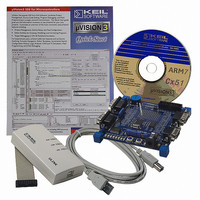
MCB2100+U NXP Semiconductors, MCB2100+U Datasheet - Page 5

MCB2100+U
Manufacturer Part Number
MCB2100+U
Description
BOARD EVAL/ULINK JTAG LPC210XARM
Manufacturer
NXP Semiconductors
Series
Keilr
Type
ARM7 Processor, Microcontrollerr
Datasheet
1.MCB2100U.pdf
(14 pages)
Specifications of MCB2100+U
Contents
Evaluation Board, ULINK JTAG, Debugger and Software
For Use With/related Products
LPC2114,2119,2124,2129,2194
Lead Free Status / RoHS Status
Not applicable / Not applicable
Other names
568-1755
OM10046
OM10046
NXP Semiconductors
3. Details of the Philips LPC2000 Flash utility
AN10302_4
Application note
Fig 2. The RTS/DTR control - an example circuit.
3.1 Manual entry into ISP mode
3.2 ISP mode entry using DTR/RTS
This flash utility is available for free download from the Philips website. This software, in
combination with the hardware described below, allows for hands-off erasure, uploading,
and execution of code.
The Philips LPC2000 Flash utility utilizes two, otherwise unused, signals (RTS and DTR)
of the PC serial port to control the microcontroller reset and P0.14 pins. The port pin
P0.14, if LOW during reset, puts the microcontroller into In System Programming (ISP)
mode; this pin has the alternate functions of external interrupt one and general purpose
I/O (GPIO). Some details on the associated circuitry will help in understanding how this
works.
With jumper J1 removed and jumper J2 in place ISP mode will be entered manually by
holding S2 while pressing and releasing S1 (reset). This can become cumbersome and so
it is advantageous to use RTS/DTR control of these signals.
With jumper J1 inserted and jumper J2 removed the reset and P0.14 signals may be
controlled by the previously un-used RTS/DTR signals of the PC serial port. In this
application both these signals are active HIGH. When RTS is asserted Q2 is turned on
and the microcontroller reset is pulled LOW. While the micro is held in reset, DTR is
asserted and P0.14 is held LOW. RTS is then brought LOW and so Q2 is turned off. The
10K pull-up resistor releases the RESET signal by pulling it HIGH. The microcontroller is
now running in ISP mode.
This sequence of ISP mode entry is performed for every operation offered by the Philips
LPC2000 Flash Utility.
RTS
DTR
Rev. 04 — 12 October 2006
Using the Philips LPC2000 Flash utility
AN10302
© NXP B.V. 2006. All rights reserved.
5 of 14


