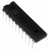
ST7FLIT19BF1B6 STMicroelectronics, ST7FLIT19BF1B6 Datasheet - Page 40

ST7FLIT19BF1B6
Manufacturer Part Number
ST7FLIT19BF1B6
Description
IC MCU 8BIT 4K FLASH 20DIP
Manufacturer
STMicroelectronics
Series
ST7r
Datasheet
1.ST7FLIT15BY1M6.pdf
(159 pages)
Specifications of ST7FLIT19BF1B6
Core Processor
ST7
Core Size
8-Bit
Speed
8MHz
Connectivity
SPI
Peripherals
LVD, POR, PWM, WDT
Number Of I /o
17
Program Memory Size
4KB (4K x 8)
Program Memory Type
FLASH
Eeprom Size
128 x 8
Ram Size
256 x 8
Voltage - Supply (vcc/vdd)
2.7 V ~ 5.5 V
Data Converters
A/D 7x10b
Oscillator Type
Internal
Operating Temperature
-40°C ~ 85°C
Package / Case
20-DIP (0.300", 7.62mm)
Processor Series
ST7FLIT1x
Core
ST7
Data Bus Width
8 bit
Data Ram Size
256 B
Interface Type
SPI
Maximum Clock Frequency
8 MHz
Number Of Programmable I/os
17
Number Of Timers
4
Operating Supply Voltage
2.7 V to 5.5 V
Maximum Operating Temperature
+ 85 C
Mounting Style
Through Hole
Development Tools By Supplier
ST7FLITE-SK/RAIS, ST7FLIT1B-D/RAIS, ST7MDT10-DVP3, ST7MDT10-EMU3, STX-RLINK
Minimum Operating Temperature
- 40 C
On-chip Adc
10 bit , 13 bit, 7 Channel
For Use With
497-6232 - BOARD EVAL ST7LITE1B,STP5NK60Z497-5049 - KIT STARTER RAISONANCE ST7FLITE497-5046 - KIT TOOL FOR ST7/UPSD/STR7 MCU
Lead Free Status / RoHS Status
Lead free / RoHS Compliant
Other names
497-5626-5
Available stocks
Company
Part Number
Manufacturer
Quantity
Price
Company:
Part Number:
ST7FLIT19BF1B6
Manufacturer:
TE
Quantity:
1 000
ST7LITE1xB
9 POWER SAVING MODES
9.1 INTRODUCTION
To give a large measure of flexibility to the applica-
tion in terms of power consumption, five main pow-
er saving modes are implemented in the ST7 (see
Figure
■
■
■
■
■
After a RESET the normal operating mode is se-
lected by default (RUN mode). This mode drives
the device (CPU and embedded peripherals) by
means of a master clock which is based on the
main oscillator frequency divided or multiplied by 2
(f
From RUN mode, the different power saving
modes may be selected by setting the relevant
register bits or by calling the specific ST7 software
instruction whose action depends on the oscillator
status.
Figure 22. Power Saving Mode Transitions
40/159
1
OSC2
AUTO WAKE UP FROM HALT
Slow
Wait (and Slow-Wait)
Active Halt
Auto Wake up From Halt (AWUFH)
Halt
).
22):
ACTIVE HALT
SLOW WAIT
POWER CONSUMPTION
SLOW
WAIT
HALT
RUN
Low
High
9.2 SLOW MODE
This mode has two targets:
– To reduce power consumption by decreasing the
– To adapt the internal clock frequency (f
SLOW mode is controlled by the SMS bit in the
MCCSR register which enables or disables Slow
mode.
In this mode, the oscillator frequency is divided by
32. The CPU and peripherals are clocked at this
lower frequency.
Note: SLOW-WAIT mode is activated when enter-
ing WAIT mode while the device is already in
SLOW mode.
Figure 23. SLOW Mode Clock Transition
internal clock in the device,
the available supply voltage.
SMS
f
CPU
f
OSC
f
OSC
NORMAL RUN MODE
/32
REQUEST
f
OSC
CPU
) to


