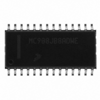
MC908JB8ADWE Freescale Semiconductor, MC908JB8ADWE Datasheet - Page 141

MC908JB8ADWE
Manufacturer Part Number
MC908JB8ADWE
Description
IC MCU 3MHZ 8K FLASH 28-SOIC
Manufacturer
Freescale Semiconductor
Series
HC08r
Datasheet
1.MC908JB8JDWE.pdf
(286 pages)
Specifications of MC908JB8ADWE
Core Processor
HC08
Core Size
8-Bit
Speed
3MHz
Connectivity
USB
Peripherals
LVD, POR, PWM
Number Of I /o
21
Program Memory Size
8KB (8K x 8)
Program Memory Type
FLASH
Ram Size
256 x 8
Voltage - Supply (vcc/vdd)
4 V ~ 5.5 V
Oscillator Type
Internal
Operating Temperature
0°C ~ 70°C
Package / Case
28-SOIC (7.5mm Width)
Processor Series
HC08JB
Core
HC08
Data Bus Width
8 bit
Data Ram Size
256 B
Interface Type
USB
Maximum Clock Frequency
3 MHz
Number Of Programmable I/os
37
Number Of Timers
2
Operating Supply Voltage
5.25 V
Maximum Operating Temperature
+ 70 C
Mounting Style
SMD/SMT
Development Tools By Supplier
FSICEBASE, DEMO908GZ60E, M68EML08GZE, KITUSBSPIDGLEVME, KITUSBSPIEVME, KIT33810EKEVME
Minimum Operating Temperature
0 C
Controller Family/series
HC08
No. Of I/o's
21
Ram Memory Size
256Byte
Cpu Speed
8MHz
No. Of Timers
1
Embedded Interface Type
SCI, SPI
Rohs Compliant
Yes
Lead Free Status / RoHS Status
Lead free / RoHS Compliant
Eeprom Size
-
Data Converters
-
Lead Free Status / Rohs Status
Lead free / RoHS Compliant
Available stocks
Company
Part Number
Manufacturer
Quantity
Price
Part Number:
MC908JB8ADWE
Manufacturer:
FREESCALE
Quantity:
20 000
- Current page: 141 of 286
- Download datasheet (2Mb)
9.8.3 USB Interrupt Register 1
MC68HC908JB8•MC68HC08JB8•MC68HC08JT8 — Rev. 2.3
Freescale Semiconductor
NOTE:
Address:
EOPF — End-of-Packet Detect Flag
RSTF — USB Reset Flag
The USB bit in the RSR register (see
also a USB reset indicator.
TXD2F — Endpoint 2 Data Transmit Flag
Reset:
Read:
Write:
This read-only bit is set when a valid end-of-packet sequence is
detected on the D+ and D– lines. Software must clear this flag by
writing a logic 1 to the EOPFR bit.
Reset clears this bit. Writing to EOPF has no effect.
This read-only bit is set when a valid reset signal state is detected on
the D+ and D– lines. If the URSTD bit of the configuration register
(CONFIG) is clear, this reset detection will generate an internal reset
signal to reset the CPU and other peripherals including the USB
module. If the URSTD bit is set, this reset detection will generate an
USB interrupt. This bit is cleared by writing a logic 1 to the RSTFR bit.
This bit also is cleared by a POR reset.
This read-only bit is set after the data stored in endpoint 2 transmit
buffers has been sent and an ACK handshake packet from the host is
received. Once the next set of data is ready in the transmit buffers,
software must clear this flag by writing a logic 1 to the TXD2FR bit.
1 = End-of-packet sequence has been detected
0 = End-of-packet sequence has not been detected
$003A
EOPF
Bit 7
Universal Serial Bus Module (USB)
0
Figure 9-17. USB Interrupt Register 1 (UIR1)
= Unimplemented
RSTF
6
0
TXD2F
5
0
RXD2F
4
0
8.8.2 Reset Status
TXD1F
Universal Serial Bus Module (USB)
3
0
RESUMF
2
0
TXD0F
Register) is
1
0
Technical Data
I/O Registers
RXD0F
Bit 0
0
141
Related parts for MC908JB8ADWE
Image
Part Number
Description
Manufacturer
Datasheet
Request
R
Part Number:
Description:
Manufacturer:
Freescale Semiconductor, Inc
Datasheet:
Part Number:
Description:
Manufacturer:
Freescale Semiconductor, Inc
Datasheet:
Part Number:
Description:
Manufacturer:
Freescale Semiconductor, Inc
Datasheet:
Part Number:
Description:
Manufacturer:
Freescale Semiconductor, Inc
Datasheet:
Part Number:
Description:
Manufacturer:
Freescale Semiconductor, Inc
Datasheet:
Part Number:
Description:
Manufacturer:
Freescale Semiconductor, Inc
Datasheet:
Part Number:
Description:
Manufacturer:
Freescale Semiconductor, Inc
Datasheet:
Part Number:
Description:
Manufacturer:
Freescale Semiconductor, Inc
Datasheet:
Part Number:
Description:
Manufacturer:
Freescale Semiconductor, Inc
Datasheet:
Part Number:
Description:
Manufacturer:
Freescale Semiconductor, Inc
Datasheet:
Part Number:
Description:
Manufacturer:
Freescale Semiconductor, Inc
Datasheet:
Part Number:
Description:
Manufacturer:
Freescale Semiconductor, Inc
Datasheet:
Part Number:
Description:
Manufacturer:
Freescale Semiconductor, Inc
Datasheet:
Part Number:
Description:
Manufacturer:
Freescale Semiconductor, Inc
Datasheet:
Part Number:
Description:
Manufacturer:
Freescale Semiconductor, Inc
Datasheet:


