MCHC912B32CFUE8 Freescale Semiconductor, MCHC912B32CFUE8 Datasheet - Page 220
MCHC912B32CFUE8
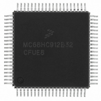
Manufacturer Part Number
MCHC912B32CFUE8
Description
IC MCU 32K FLASH 8MHZ 80-QFP
Manufacturer
Freescale Semiconductor
Series
HC12r
Datasheet
1.MCHC912B32CFUE8.pdf
(334 pages)
Specifications of MCHC912B32CFUE8
Core Processor
CPU12
Core Size
16-Bit
Speed
8MHz
Connectivity
SCI, SPI
Peripherals
POR, PWM, WDT
Number Of I /o
63
Program Memory Size
32KB (32K x 8)
Program Memory Type
FLASH
Eeprom Size
768 x 8
Ram Size
1K x 8
Voltage - Supply (vcc/vdd)
4.5 V ~ 5.5 V
Data Converters
A/D 8x10b
Oscillator Type
External
Operating Temperature
-40°C ~ 85°C
Package / Case
80-QFP
Cpu Family
HC12
Device Core Size
16b
Frequency (max)
8MHz
Interface Type
SCI/SPI
Total Internal Ram Size
1KB
# I/os (max)
63
Operating Supply Voltage (typ)
5V
Operating Supply Voltage (max)
5.5V
Operating Supply Voltage (min)
4.5V
On-chip Adc
8-chx10-bit
Instruction Set Architecture
CISC
Operating Temp Range
-40C to 85C
Operating Temperature Classification
Industrial
Mounting
Surface Mount
Pin Count
80
Package Type
PQFP
Package
80PQFP
Family Name
HC12
Maximum Speed
8 MHz
Operating Supply Voltage
5 V
Data Bus Width
16 Bit
Number Of Programmable I/os
63
Processor Series
HC912B
Core
HC12
Data Ram Size
1 KB
Maximum Clock Frequency
8 MHz
Maximum Operating Temperature
+ 85 C
Mounting Style
SMD/SMT
3rd Party Development Tools
EWHCS12
Development Tools By Supplier
M68EVB912B32E
Minimum Operating Temperature
- 40 C
Lead Free Status / RoHS Status
Lead free / RoHS Compliant
Available stocks
Company
Part Number
Manufacturer
Quantity
Price
Company:

Part Number:
MCHC912B32CFUE8
Manufacturer:
Freescale Semiconductor
Quantity:
10 000


Byte Data Link Communications (BDLC)
15.7.2.2 Data — In-Message Data Bytes
The data bytes contained in the message include the message priority/type, message ID byte (typically,
the physical address of the responder), and any actual data being transmitted to the receiving node. The
message format used by the BDLC is similar to the 3-byte consolidated header message format outlined
by the SAE J1850 document. See SAE J1850 – Class B Data Communications Network Interface
specification for more information about 1- and 3-byte headers.
Messages transmitted by the BDLC onto the J1850 bus must contain at least one data byte, and,
therefore, can be as short as one data byte and one CRC byte. Each data byte in the message is eight
bits in length and is transmitted MSB (most significant bit) to LSB (least significant bit).
15.7.2.3 CRC — Cyclical Redundancy Check Byte
This byte is used by the receiver(s) of each message to determine if any errors have occurred during the
transmission of the message. The BDLC calculates the CRC byte and appends it onto any messages
transmitted onto the J1850 bus. It also performs CRC detection on any messages it receives from the
J1850 bus.
8
4
3
2
CRC generation uses the divisor polynomial X
+ X
+ X
+ X
+ 1. The remainder polynomial initially is
set to all 1s. Each byte in the message after the start-of-frame (SOF) symbol is processed serially through
the CRC generation circuitry. The one’s complement of the remainder then becomes the 8-bit CRC byte,
which is appended to the message after the data bytes, in MSB-to-LSB order.
When receiving a message, the BDLC uses the same divisor polynomial. All data bytes, excluding the
SOF and end-of-data symbols (EOD) but including the CRC byte, are used to check the CRC. If the
message is error free, the remainder polynomial equals
7
6
2
X
+ X
+ X
= $C4, regardless of the data contained in the message. If the calculated CRC does not equal
$C4, the BDLC recognizes this as a CRC error and sets the CRC error flag in the BSVR.
15.7.2.4 EOD — End-of-Data Symbol
The EOD symbol is a long 200-µs passive period on the J1850 bus used to signify to any recipients of a
message that the transmission by the originator has completed. No flag is set upon reception of the EOD
symbol.
15.7.2.5 IFR — In-Frame Response Bytes
The IFR section of the J1850 message format is optional. Users desiring further definition of in-frame
response should review the SAE J1850 – Class B Data Communications Network Interface specification.
15.7.2.6 EOF — End-of-Frame Symbol
This symbol is a long 280-µs passive period on the J1850 bus and is longer than an end-of-data (EOD)
symbol, which signifies the end of a message. Since an EOF symbol is longer than a 200-µs EOD symbol,
if no response is transmitted after an EOD symbol, it becomes an EOF, and the message is assumed to
be completed. The EOF flag is set upon receiving the EOF symbol.
15.7.2.7 IFS — Interframe Separation Symbol
The IFS symbol is a 20-µs passive period on the J1850 bus which allows proper synchronization between
nodes during continuous message transmission. The IFS symbol is transmitted by a node after the
completion of the end-of-frame (EOF) period and, therefore, is seen as a 300-µs passive period.
M68HC12B Family Data Sheet, Rev. 9.1
220
Freescale Semiconductor
Related parts for MCHC912B32CFUE8
Image
Part Number
Description
Manufacturer
Datasheet
Request
R

Part Number:
Description:
Manufacturer:
Freescale Semiconductor, Inc
Datasheet:
Part Number:
Description:
Manufacturer:
Freescale Semiconductor, Inc
Datasheet:
Part Number:
Description:
Manufacturer:
Freescale Semiconductor, Inc
Datasheet:
Part Number:
Description:
Manufacturer:
Freescale Semiconductor, Inc
Datasheet:
Part Number:
Description:
Manufacturer:
Freescale Semiconductor, Inc
Datasheet:
Part Number:
Description:
Manufacturer:
Freescale Semiconductor, Inc
Datasheet:
Part Number:
Description:
Manufacturer:
Freescale Semiconductor, Inc
Datasheet:
Part Number:
Description:
Manufacturer:
Freescale Semiconductor, Inc
Datasheet:
Part Number:
Description:
Manufacturer:
Freescale Semiconductor, Inc
Datasheet:
Part Number:
Description:
Manufacturer:
Freescale Semiconductor, Inc
Datasheet:
Part Number:
Description:
Manufacturer:
Freescale Semiconductor, Inc
Datasheet:
Part Number:
Description:
Manufacturer:
Freescale Semiconductor, Inc
Datasheet:
Part Number:
Description:
Manufacturer:
Freescale Semiconductor, Inc
Datasheet:
Part Number:
Description:
Manufacturer:
Freescale Semiconductor, Inc
Datasheet:
Part Number:
Description:
Manufacturer:
Freescale Semiconductor, Inc
Datasheet: