MCHC912B32CFUE8 Freescale Semiconductor, MCHC912B32CFUE8 Datasheet - Page 227
MCHC912B32CFUE8
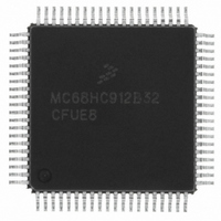
Manufacturer Part Number
MCHC912B32CFUE8
Description
IC MCU 32K FLASH 8MHZ 80-QFP
Manufacturer
Freescale Semiconductor
Series
HC12r
Datasheet
1.MCHC912B32CFUE8.pdf
(334 pages)
Specifications of MCHC912B32CFUE8
Core Processor
CPU12
Core Size
16-Bit
Speed
8MHz
Connectivity
SCI, SPI
Peripherals
POR, PWM, WDT
Number Of I /o
63
Program Memory Size
32KB (32K x 8)
Program Memory Type
FLASH
Eeprom Size
768 x 8
Ram Size
1K x 8
Voltage - Supply (vcc/vdd)
4.5 V ~ 5.5 V
Data Converters
A/D 8x10b
Oscillator Type
External
Operating Temperature
-40°C ~ 85°C
Package / Case
80-QFP
Cpu Family
HC12
Device Core Size
16b
Frequency (max)
8MHz
Interface Type
SCI/SPI
Total Internal Ram Size
1KB
# I/os (max)
63
Operating Supply Voltage (typ)
5V
Operating Supply Voltage (max)
5.5V
Operating Supply Voltage (min)
4.5V
On-chip Adc
8-chx10-bit
Instruction Set Architecture
CISC
Operating Temp Range
-40C to 85C
Operating Temperature Classification
Industrial
Mounting
Surface Mount
Pin Count
80
Package Type
PQFP
Package
80PQFP
Family Name
HC12
Maximum Speed
8 MHz
Operating Supply Voltage
5 V
Data Bus Width
16 Bit
Number Of Programmable I/os
63
Processor Series
HC912B
Core
HC12
Data Ram Size
1 KB
Maximum Clock Frequency
8 MHz
Maximum Operating Temperature
+ 85 C
Mounting Style
SMD/SMT
3rd Party Development Tools
EWHCS12
Development Tools By Supplier
M68EVB912B32E
Minimum Operating Temperature
- 40 C
Lead Free Status / RoHS Status
Lead free / RoHS Compliant
Available stocks
Company
Part Number
Manufacturer
Quantity
Price
Company:

Part Number:
MCHC912B32CFUE8
Manufacturer:
Freescale Semiconductor
Quantity:
10 000


15.7.4.11 Valid BREAK Symbol
In
symbol is considered a valid BREAK symbol. A BREAK symbol should be followed by a start-of-frame
(SOF) symbol beginning the next message to be transmitted onto the J1850 bus. See
Frame Format
15.7.5 Message Arbitration
Message arbitration on the J1850 bus is accomplished in a non-destructive manner, allowing the
message with the highest priority to be transmitted, while any transmitters which lose arbitration simply
stop transmitting and wait for an idle bus to begin transmitting again.
If the BDLC wants to transmit onto the J1850 bus, but detects that another message is in progress, it waits
until the bus is idle. However, if multiple nodes begin to transmit in the same synchronization window,
message arbitration occurs beginning with the first bit after the SOF symbol and continues with each bit
thereafter. If a write to the BDR (for instance, to initiate transmission) occurred on or before
104 • t
write to the BDR occurred after
104 • t
IFS period to expire before attempting to transmit the byte.
The variable pulse-width modulation (VPW) symbols and J1850 bus electrical characteristics are chosen
carefully so that a logic 0 (active or passive type) always dominates over a logic 1 (active or passive type)
simultaneously transmitted. Hence, logic 0s are said to be dominant and logic 1s are said to be recessive.
When a node detects a dominant bit on BDRxD when it transmitted a recessive bit, it loses arbitration and
immediately stops transmitting. This is known as bitwise arbitration (see
Since a logic 0 dominates a logic 1, the message with the lowest value has the highest priority and
always wins arbitration. For instance, a message with priority 000 wins arbitration over a message with
priority 011.
This method of arbitration works no matter how many bits of priority encoding are contained in the
message.
During arbitration, or even throughout the transmitting message, when an opposite bit is detected,
transmission is stopped immediately unless it occurs on the eighth bit of a byte. In this case, the BDLC
automatically appends up to two extra logic 1 bits and then stops transmitting. These two extra bits are
arbitrated normally and thus do not interfere with another message. The second logic 1 bit is not sent if
Freescale Semiconductor
Figure
BDLC
BDLC
15-9, if the next active-to-passive received transition does not occur until after E, the current
from the detection of the rising edge, then the BDLC does not transmit, but waits for the next
from the received rising edge, then the BDLC transmits and arbitrates for the bus. If a CPU
ACTIVE
PASSIVE
for BDLC response to BREAK symbols.
Figure 15-9. J1850 VPW Received BREAK Symbol Times
240 µs
M68HC12B Family Data Sheet, Rev. 9.1
E
Figure
(2) VALID BREAK SYMBOL
15-10).
BDLC MUX Interface
15.7.2 J1850
227
Related parts for MCHC912B32CFUE8
Image
Part Number
Description
Manufacturer
Datasheet
Request
R

Part Number:
Description:
Manufacturer:
Freescale Semiconductor, Inc
Datasheet:
Part Number:
Description:
Manufacturer:
Freescale Semiconductor, Inc
Datasheet:
Part Number:
Description:
Manufacturer:
Freescale Semiconductor, Inc
Datasheet:
Part Number:
Description:
Manufacturer:
Freescale Semiconductor, Inc
Datasheet:
Part Number:
Description:
Manufacturer:
Freescale Semiconductor, Inc
Datasheet:
Part Number:
Description:
Manufacturer:
Freescale Semiconductor, Inc
Datasheet:
Part Number:
Description:
Manufacturer:
Freescale Semiconductor, Inc
Datasheet:
Part Number:
Description:
Manufacturer:
Freescale Semiconductor, Inc
Datasheet:
Part Number:
Description:
Manufacturer:
Freescale Semiconductor, Inc
Datasheet:
Part Number:
Description:
Manufacturer:
Freescale Semiconductor, Inc
Datasheet:
Part Number:
Description:
Manufacturer:
Freescale Semiconductor, Inc
Datasheet:
Part Number:
Description:
Manufacturer:
Freescale Semiconductor, Inc
Datasheet:
Part Number:
Description:
Manufacturer:
Freescale Semiconductor, Inc
Datasheet:
Part Number:
Description:
Manufacturer:
Freescale Semiconductor, Inc
Datasheet:
Part Number:
Description:
Manufacturer:
Freescale Semiconductor, Inc
Datasheet: