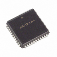
DS87C520-QNL+T&R Maxim Integrated Products, DS87C520-QNL+T&R Datasheet - Page 13

DS87C520-QNL+T&R
Manufacturer Part Number
DS87C520-QNL+T&R
Description
IC MCU EPROM/ROM 33MH IND 44PLCC
Manufacturer
Maxim Integrated Products
Series
87Cr
Datasheet
1.DS87C520-QCL.pdf
(43 pages)
Specifications of DS87C520-QNL+T&R
Core Processor
8051
Core Size
8-Bit
Speed
33MHz
Connectivity
EBI/EMI, SIO, UART/USART
Peripherals
Power-Fail Reset, WDT
Number Of I /o
32
Program Memory Size
16KB (16K x 8)
Program Memory Type
OTP
Ram Size
1K x 8
Voltage - Supply (vcc/vdd)
4.5 V ~ 5.5 V
Oscillator Type
External
Operating Temperature
-40°C ~ 85°C
Package / Case
44-LCC, 44-PLCC
Processor Series
DS87C520
Core
8051
Data Bus Width
8 bit
Data Ram Size
1 KB
Interface Type
UART
Maximum Clock Frequency
33 MHz
Number Of Programmable I/os
32
Number Of Timers
3
Operating Supply Voltage
4.5 V to 5.5 V
Maximum Operating Temperature
+ 85 C
Mounting Style
SMD/SMT
3rd Party Development Tools
PK51, CA51, A51, ULINK2
Minimum Operating Temperature
- 40 C
Package
44PLCC
Device Core
8051
Family Name
87C
Maximum Speed
33 MHz
Lead Free Status / RoHS Status
Lead free / RoHS Compliant
Eeprom Size
-
Data Converters
-
Lead Free Status / Rohs Status
Details
setting. When desiring maximum speed, software should select a Stretch value of 0. When using very
slow RAM or peripherals, select a larger Stretch value. Note that this affects data memory only and the
only way to slow program memory (ROM) access is to use a slower crystal.
Using a Stretch value between 1 and 7 causes the microcontroller to stretch the read/write strobe and all
related timing. Also, setup and hold times are increased by 1 clock when using any Stretch greater than 0.
This results in a wider read/write strobe and relaxed interface timing, allowing more time for
memory/peripherals to respond. The timing of the variable speed MOVX is in the Electrical
Specifications section. Table 3 shows the resulting strobe widths for each Stretch value. The memory
Stretch uses the Clock Control Special Function Register at SFR location 8Eh. The Stretch value is
selected using bits CKCON.2–0. In the table, these bits are referred to as M2 through M0. The first
Stretch (default) allows the use of common 120ns RAMs without dramatically lengthening the memory
access.
Table 3. Data Memory Cycle Stretch Values
DUAL DATA POINTER
The timing of block moves of data memory is faster using the Dual Data Pointer (DPTR). The standard
8051 DPTR is a 16-bit value that is used to address off-chip data RAM or peripherals. In the
DS87C520/DS83C520, this data pointer is called DPTR0, located at SFR addresses 82h and 83h. These
are the original locations. Using DPTR requires no modification of standard code. The new DPTR at SFR
84h and 85h is called DPTR1. The DPTR Select bit (DPS) chooses the active pointer. Its location is the
lsb of the SFR location 86h. No other bits in register 86h have any effect and are 0. The user switches
between data pointers by toggling the lsb of register 86h. The increment (INC) instruction is the fastest
way to accomplish this. All DPTR-related instructions use the currently selected DPTR for any activity.
Therefore it takes only one instruction to switch from a source to a destination address. Using the Dual
Data Pointer saves code from needing to save source and destination addresses when doing a block move.
The software simply switches between DPTR0 and 1 once software loads them. The relevant register
locations are as follows:
M2
0
0
0
0
1
1
1
1
CKCON.2-0
M1
0
0
1
1
0
0
1
1
M0
0
1
0
1
0
1
0
1
DPL
DPH 83h
DPL1 84h
DPH1 85h
DPS
MEMORY CYCLES
3 (default external)
2 (forced internal)
82h
86h
4
5
6
7
8
9
DS87C520/DS83C520 EPROM/ROM High-Speed Microcontrollers
Low byte original DPTR
High byte original DPTR
Low byte new DPTR
High byte new DPTR
DPTR Select (lsb)
13 of 43
RD OR WR STROBE
WIDTH IN CLOCKS
12
16
20
24
28
2
4
8
TIME at 33MHz (ns)
STROBE WIDTH
121
242
364
485
606
727
848
60


