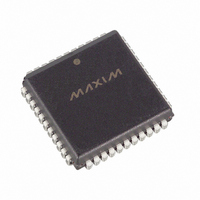
DS87C520-QNL+T&R Maxim Integrated Products, DS87C520-QNL+T&R Datasheet - Page 7

DS87C520-QNL+T&R
Manufacturer Part Number
DS87C520-QNL+T&R
Description
IC MCU EPROM/ROM 33MH IND 44PLCC
Manufacturer
Maxim Integrated Products
Series
87Cr
Datasheet
1.DS87C520-QCL.pdf
(43 pages)
Specifications of DS87C520-QNL+T&R
Core Processor
8051
Core Size
8-Bit
Speed
33MHz
Connectivity
EBI/EMI, SIO, UART/USART
Peripherals
Power-Fail Reset, WDT
Number Of I /o
32
Program Memory Size
16KB (16K x 8)
Program Memory Type
OTP
Ram Size
1K x 8
Voltage - Supply (vcc/vdd)
4.5 V ~ 5.5 V
Oscillator Type
External
Operating Temperature
-40°C ~ 85°C
Package / Case
44-LCC, 44-PLCC
Processor Series
DS87C520
Core
8051
Data Bus Width
8 bit
Data Ram Size
1 KB
Interface Type
UART
Maximum Clock Frequency
33 MHz
Number Of Programmable I/os
32
Number Of Timers
3
Operating Supply Voltage
4.5 V to 5.5 V
Maximum Operating Temperature
+ 85 C
Mounting Style
SMD/SMT
3rd Party Development Tools
PK51, CA51, A51, ULINK2
Minimum Operating Temperature
- 40 C
Package
44PLCC
Device Core
8051
Family Name
87C
Maximum Speed
33 MHz
Lead Free Status / RoHS Status
Lead free / RoHS Compliant
Eeprom Size
-
Data Converters
-
Lead Free Status / Rohs Status
Details
DS87C520/DS83C520 EPROM/ROM High-Speed Microcontrollers
COMPATIBILITY
The DS87C520/DS83C520 are fully static CMOS 8051-compatible microcontrollers designed for high
performance. In most cases, the DS87C520/DS83C520 can drop into an existing socket for the 8xc51
family to improve the operation significantly. While remaining familiar to 8051 family users, the devices
have many new features. In general, software written for existing 8051-based systems works without
modification on the DS87C520/DS83C520. The exception is critical timing since the high-speed
microcontrollers performs instructions much faster than the original for any given crystal selection. The
DS87C520/DS83C520 run the standard 8051 family instruction set and are pin compatible with DIP,
PLCC, or TQFP packages.
The DS87C520/DS83C520 provide three 16-bit timer/counters, full-duplex serial port (2), 256 bytes of
direct RAM plus 1kB of extra MOVX RAM. I/O ports have the same operation as a standard 8051
product. Timers will default to a 12-clock per cycle operation to keep their timing compatible with
original 8051 family systems. However, timers are individually programmable to run at the new four
clocks per cycle if desired. The PCA is not supported.
The DS87C520/DS83C520 provide several new hardware features implemented by new special function
registers. A summary of these SFRs is provided below.
PERFORMANCE OVERVIEW
The DS87C520/DS83C520 feature a high-speed 8051-compatible core. Higher speed comes not just from
increasing the clock frequency but also from a newer, more efficient design.
This updated core does not have the dummy memory cycles that are present in a standard 8051. A
conventional 8051 generates machine cycles using the clock frequency divided by 12. In the
DS87C520/DS83C520, the same machine cycle takes 4 clocks. Thus the fastest instruction, 1 machine
cycle, executes three times faster for the same crystal frequency. Note that these are identical instructions.
The majority of instructions on the DS87C520/DS83C520 will see the full 3-to-1 speed improvement.
Some instructions will get between 1.5 and 2.4 to 1 improvement. All instructions are faster than the
original 8051.
The numerical average of all opcodes gives approximately a 2.5 to 1 speed improvement. Improvement of
individual programs will depend on the actual instructions used. Speed-sensitive applications would make
the most use of instructions that are three times faster. However, the sheer number of 3 to 1 improved
opcodes makes dramatic speed improvements likely for any code. These architecture improvements
produce a peak instruction cycle in 121ns (8.25 MIPs). The Dual Data Pointer feature also allows the user
to eliminate wasted instructions when moving blocks of memory.
INSTRUCTION SET SUMMARY
All instructions perform the same functions as their 8051 counterparts. Their effect on bits, flags, and
other status functions is identical. However, the timing of each instruction is different. This applies both
in absolute and relative number of clocks.
For absolute timing of real-time events, the timing of software loops can be calculated using a table in the
High-Speed Microcontroller User’s Guide. However, counter/timers default to run at the older 12 clocks
per increment. In this way, timer-based events occur at the standard intervals with software executing at
higher speed. Timers optionally can run at 4 clocks per increment to take advantage of faster processor
operation.
7 of 43


