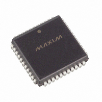
DS87C520-QNL+T&R Maxim Integrated Products, DS87C520-QNL+T&R Datasheet - Page 23

DS87C520-QNL+T&R
Manufacturer Part Number
DS87C520-QNL+T&R
Description
IC MCU EPROM/ROM 33MH IND 44PLCC
Manufacturer
Maxim Integrated Products
Series
87Cr
Datasheet
1.DS87C520-QCL.pdf
(43 pages)
Specifications of DS87C520-QNL+T&R
Core Processor
8051
Core Size
8-Bit
Speed
33MHz
Connectivity
EBI/EMI, SIO, UART/USART
Peripherals
Power-Fail Reset, WDT
Number Of I /o
32
Program Memory Size
16KB (16K x 8)
Program Memory Type
OTP
Ram Size
1K x 8
Voltage - Supply (vcc/vdd)
4.5 V ~ 5.5 V
Oscillator Type
External
Operating Temperature
-40°C ~ 85°C
Package / Case
44-LCC, 44-PLCC
Processor Series
DS87C520
Core
8051
Data Bus Width
8 bit
Data Ram Size
1 KB
Interface Type
UART
Maximum Clock Frequency
33 MHz
Number Of Programmable I/os
32
Number Of Timers
3
Operating Supply Voltage
4.5 V to 5.5 V
Maximum Operating Temperature
+ 85 C
Mounting Style
SMD/SMT
3rd Party Development Tools
PK51, CA51, A51, ULINK2
Minimum Operating Temperature
- 40 C
Package
44PLCC
Device Core
8051
Family Name
87C
Maximum Speed
33 MHz
Lead Free Status / RoHS Status
Lead free / RoHS Compliant
Eeprom Size
-
Data Converters
-
Lead Free Status / Rohs Status
Details
POWER-FAIL INTERRUPT
The voltage reference that sets a precise reset threshold also generates an optional early warning Power-
Fail Interrupt (PFI). When enabled by software, the processor will vector to program memory address
0033h if V
SFR (WDCON–D8h). Setting WDCON.5 to a logic 1 will enable the PFI. Application software can also
read the PFI flag at WDCON.4. A PFI condition sets this bit to a 1. The flag is independent of the
interrupt enable and software must manually clear it.
WATCHDOG TIMER
To prevent software from losing control, the DS87C520/DS83C520 include a programmable Watchdog
Timer. The Watchdog is a free-running timer that sets a flag if allowed to reach a preselected timeout. It
can be (re)started by software.
A typical application is to select the flag as a reset source. When the Watchdog times out, it sets its flag,
which generates reset. Software must restart the timer before it reaches its timeout or the processor is
reset.
Software can select one of four timeout values. Then, it restarts the timer and enables the reset function.
After enabling the reset function, software must then restart the timer before its expiration or hardware
will reset the CPU. Both the Watchdog Reset Enable and the Watchdog Restart control bits are protected
by a “Timed Access” circuit. This prevents errant software from accidentally clearing the Watchdog.
Timeout values are precise since they are a function of the crystal frequency as shown in Table 7. For
reference, the time periods at 33MHz also are shown.
The Watchdog also provides a useful option for systems that do not require a reset circuit. It will set an
interrupt flag 512 clocks before setting the reset flag. Software can optionally enable this interrupt source.
The interrupt is independent of the reset. A common use of the interrupt is during debug, to show
developers where the Watchdog times out. This indicates where the Watchdog must be restarted by
software. The interrupt also can serve as a convenient time-base generator or can wake-up the processor
from power saving modes.
The Watchdog function is controlled by the Clock Control (CKCON-8Eh), Watchdog Control (WDCON-
D8h), and Extended Interrupt Enable (EIE-E8h) SFRs. CKCON.7 and CKCON.6 are WD1 and WD0
respectively and they select the Watchdog timeout period as shown in Table 7.
Table 7. Watchdog Timeout Values
As shown in Table 7, the Watchdog Timer uses the crystal frequency as a time base. A user selects one of
four counter values to determine the timeout. These clock counter lengths are 2
2
with a 33MHz crystal frequency. Once the counter chain has completed a full interrupt count, hardware
20
WD1
0
0
1
1
= 1,048,576; 2
WD2
CC
0
1
0
1
drops below V
23
INTERRUPT
= 8,388,608 clocks; and 2
TIMEOUT
2
2
2
2
17
20
23
26
clocks
clocks
clocks
clocks
PFW
. PFI has the highest priority. The PFI enable is in the Watchdog Control
TIME (33 MHz)
DS87C520/DS83C520 EPROM/ROM High-Speed Microcontrollers
2033.60 ms
3.9718 ms
254.20 ms
31.77 ms
26
23 of 43
= 67,108,864 clocks. The times shown in Table 7 are
RESET TIMEOUT
2
2
2
2
17
20
23
26
+ 512 clocks
+ 512 clocks
+ 512 clocks
+ 512 clocks
17
TIME (33 MHz)
= 131,072 clocks;
2033.62 ms
3.9874 ms
254.21 ms
31.79 ms


