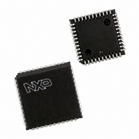
PXAG49KFA/00,512 NXP Semiconductors, PXAG49KFA/00,512 Datasheet - Page 11

PXAG49KFA/00,512
Manufacturer Part Number
PXAG49KFA/00,512
Description
IC XA MCU 16BIT FLASH 64K 44PLCC
Manufacturer
NXP Semiconductors
Series
XAr
Datasheet
1.PXAG49KBA00512.pdf
(42 pages)
Specifications of PXAG49KFA/00,512
Core Processor
XA
Core Size
16-Bit
Speed
30MHz
Connectivity
UART/USART
Peripherals
PWM, WDT
Number Of I /o
32
Program Memory Size
64KB (64K x 8)
Program Memory Type
FLASH
Ram Size
2K x 8
Voltage - Supply (vcc/vdd)
4.75 V ~ 5.25 V
Oscillator Type
External
Operating Temperature
-40°C ~ 85°C
Package / Case
44-PLCC
Lead Free Status / RoHS Status
Lead free / RoHS Compliant
Eeprom Size
-
Data Converters
-
Other names
568-1098-5
935267441512
PXAG49KFA
935267441512
PXAG49KFA
Available stocks
Company
Part Number
Manufacturer
Quantity
Price
Company:
Part Number:
PXAG49KFA/00,512
Manufacturer:
NXP Semiconductors
Quantity:
10 000
Philips Semiconductors
FMIDLE
The FMIDLE bit in the AUXR register allows saving additional power
by turning off the Flash memory when the CPU is in the Idle mode.
This must be done just prior to initiating the Idle mode, as shown
below.
When the Flash memory is put into the Idle mode by setting FMIDLE,
restarting the CPU upon exiting Idle mode takes slightly longer,
about 3 microseconds. However, the standby current consumed by
the Flash memory is reduced from about 8mA to about 1mA.
Default Loader
A default loader that accepts programming commands in a
predetermined format is contained permanently in the Boot ROM. A
factory fresh device will enter this loader automatically if it is
powered up without first being programmed by the user. Loader
commands include functions such as erase block; program Flash
memory; read Flash memory; and blank check.
Boot Vector
The XA-G49 contains two special FLASH registers: the BOOT
VECTOR and the STATUS BYTE.
The “Boot Vector” allows forcing the execution of a user supplied
Flash loader upon reset, under two specific sets of conditions. At the
falling edge of reset, the XA-G49 examines the contents of the
Status Byte. If the Status Byte is set to zero, power-up execution
starts at location 0000H, which is the normal start address of the
user’s application code.
2001 Jun 27
XA 16-bit microcontroller family
64K Flash/2K RAM, watchdog, 2 UARTs
OR
OR
.
AUXR,#$40
PCON,#$01
.
; Set Flash memory
; Turn on Idle mode.
; Execution resumes
to idle mode.
here when Idle
mode terminates.
PROGRAM
ADDRESS
Figure 3. Flash Memory Configuration
FFFF
C000
8000
4000
2000
0000
16k BYTES
16k BYTES
16k BYTES
8k BYTES
8k BYTES
BLOCK 4
BLOCK 3
BLOCK 2
BLOCK 1
BLOCK 0
11
which corresponds to the address F900h for the factory masked-ROM
When the Status Byte is set to a value other than zero, the Boot
Vector is used as the reset vector (4 bytes), including the Boot
Program Counter (BPC) and the Boot PSW (BPSW). The factory
default settings are 8000h for the BPSW and F800h for the BPC,
ISP boot loader. The Status Byte is automatically set to a non-zero
value when a programming error occurs. A custom boot loader can
be written with the Boot Vector set to the custom boot loader.
Hardware Activation of the Boot Vector
Program execution at the Boot Vector may also be forced from
outside of the microcontroller by setting the correct state on a few
pins. While Reset is asserted, the PSEN pin must be pulled low, the
ALE pin allowed to float high (need not be pulled up externally), and
the EA pin driven to a logic high (or up to V
released. This is the same effect as having a non-zero status byte.
This allows building an application that will normally execute the end
user’s code but can be manually forced into ISP operation. The Boot
ROM is enabled when use of the Boot Vector is forced as described
above, so the branch may go to the default loader. Conversely, user
code in the top 2 kbytes of the Flash memory may not be executed
when the Boot Vector is used.
If the factory default setting for the BPC (F800h) is changed, it will no
longer point to the ISP masked-ROM boot loader code. If this happens,
the only possible way to change the contents of the Boot Vector is
through the parallel programming method, provided that the end user
application does not contain a customized loader that provides for
erasing and reprogramming of the Boot Vector and Status Byte.
After programming the FLASH, the status byte should be erased to
zero in order to allow execution of the user’s application code
beginning at address 0000H.
NOTE: When erasing the Status Byte or Boot Vector, these
bytes are erased at the same time. It is necessary to reprogram
the Boot Vector after erasing and updating the Status Byte.
BOOT ROM
SU01034
FFFF
F800
PP
). Then reset may be
XA-G49
Preliminary data


