ATAB5423-3-WB Atmel, ATAB5423-3-WB Datasheet - Page 20
ATAB5423-3-WB
Manufacturer Part Number
ATAB5423-3-WB
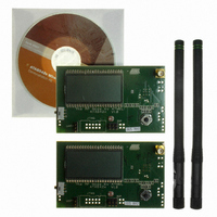
Description
KIT DEMO 315MHZ BLACKBIRD
Manufacturer
Atmel
Type
Transceiver, UHFr
Specifications of ATAB5423-3-WB
Frequency
315MHz
Product
RF Modules
For Use With/related Products
ATA5423
Lead Free Status / RoHS Status
Lead free / RoHS Compliant
Other names
ATAB-5423-3-WB


Figure 3-9.
3.12
20
Output Power Setting and PA Matching at RF_OUT
ATA5423/ATA5425/ATA5428/ATA5429
Ref 10 dB
W1 S2
FSK-modulated TX Spectrum (433.92 MHz/20 Kbit/s/±16.17 kHz/Manchester Code)
S3 FC
Samp
VAvg
Log
dB/
Center 433.92 MHz
Res BW 10 kHz
10
50
The Power Amplifier (PA) is a single-ended open collector stage which delivers a current pulse
which is nearly independent of supply voltage, temperature and tolerances due to band gap sta-
bilization. Resistor R
current in the PA. A higher resistor value results in a lower reference current, a lower output
power and a lower current consumption of the PA. The usable range of R
PWR_H switches the output power range between about 0 dBm to 5 dBm (PWR_H = GND) and
5 dBm to 10 dBm (PWR_H = AVCC) by multiplying this reference current by a factor 1
(PWR_H = GND) and 2.5 (PWR_H = AVCC), which corresponds to about 5 dB more output
power.
If the PA is switched off in TX mode, the current consumption without output stage with
VS1 = VS2 = 3 V, T
433.92 MHz.
The maximum output power is achieved with optimum load resistances R
3-7 on page 22
absorbing it into the matching network consisting of L
21. There must also be a low resistive DC path to AVCC to deliver the DC current of the power
amplifier's last stage. The matching of the PA output was done with the circuit shown in
3-10 on page 21
ments may be necessary to compensate for individual board layouts.
with compensation of the 1.0 pF output capacitance of the RF_OUT pin by
with the values in
Atten 20 dB
amb
1
, see
= 25°C is typically 6.5 mA for 868.3 MHz and 6.95 mA for 315 MHz and
Figure 3-10 on page
VBW 10 kHz
Table 3-7 on page
21, sets a reference current which controls the
1
, C
22. Note that value changes of these ele-
1
, C
3
Span 1 MHz
Sweep 27.5 ms (401 pts)
as shown in
1
Lopt
is 15 k to 56 k . Pin
Figure 3-10 on page
according to
4841D–WIRE–10/07
Figure
Table
Related parts for ATAB5423-3-WB
Image
Part Number
Description
Manufacturer
Datasheet
Request
R

Part Number:
Description:
BOARD BASESTATN UHF RCVR 315MHZ
Manufacturer:
Atmel
Datasheet:

Part Number:
Description:
DEV KIT FOR AVR/AVR32
Manufacturer:
Atmel
Datasheet:

Part Number:
Description:
INTERVAL AND WIPE/WASH WIPER CONTROL IC WITH DELAY
Manufacturer:
ATMEL Corporation
Datasheet:
Part Number:
Description:
Low-Voltage Voice-Switched IC for Hands-Free Operation
Manufacturer:
ATMEL Corporation
Datasheet:
Part Number:
Description:
MONOLITHIC INTEGRATED FEATUREPHONE CIRCUIT
Manufacturer:
ATMEL Corporation
Datasheet:
Part Number:
Description:
AM-FM Receiver IC U4255BM-M
Manufacturer:
ATMEL Corporation
Datasheet:
Part Number:
Description:
Monolithic Integrated Feature Phone Circuit
Manufacturer:
ATMEL Corporation
Datasheet:
Part Number:
Description:
Multistandard Video-IF and Quasi Parallel Sound Processing
Manufacturer:
ATMEL Corporation
Datasheet:
Part Number:
Description:
High-performance EE PLD
Manufacturer:
ATMEL Corporation
Datasheet:
Part Number:
Description:
8-bit Flash Microcontroller
Manufacturer:
ATMEL Corporation
Datasheet:
Part Number:
Description:
2-Wire Serial EEPROM
Manufacturer:
ATMEL Corporation
Datasheet: