ATAB5423-3-WB Atmel, ATAB5423-3-WB Datasheet - Page 57
ATAB5423-3-WB
Manufacturer Part Number
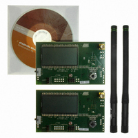
ATAB5423-3-WB
Description
KIT DEMO 315MHZ BLACKBIRD
Manufacturer
Atmel
Type
Transceiver, UHFr
Specifications of ATAB5423-3-WB
Frequency
315MHz
Product
RF Modules
For Use With/related Products
ATA5423
Lead Free Status / RoHS Status
Lead free / RoHS Compliant
Other names
ATAB-5423-3-WB


Figure 9-5.
4841D–WIRE–10/07
Bit-check counter
(Lim_min = 14, Lim_max = 24)
RX_ACTIVE
Demod_Out
Timing Diagram During Bit Check
Bit check
T
Start-up mode
Startup_Sig_Proc
For the best noise immunity, use of a low span between T
This is achieved using a fixed frequency at a 50% duty cycle for the transmitter preburst: a
“11111...” or a “10101...” sequence in Manchester or Bi-phase is a good choice. A good compro-
mise between sensitivity and susceptibility to noise regarding the expected edge-to-edge time,
t
and then N
the bit-check limits must be programmed according to the required span.
The bit-check limits are determined by means of the formula below:
Lim_min is defined by the bits Lim_min 0 to Lim_min 5 in control register 5.
Lim_max is defined by the bits Lim_max 0 to Lim_max 5 in control register 6.
Using the above formulas, Lim_min and Lim_max can be determined according to the required
T
minimum edge-to-edge time t
lower limit should be set to Lim_min
Lim_max = 63.
Figure
Lim_min = 14 and Lim_max = 24. The signal processing circuits are enabled during T
and T
that period. When the bit check becomes active, the bit-check counter is clocked with the cycle
T
Figure 9-5
limits defined by Lim_min and Lim_max at the occurrence of a signal edge. In
page 58
check also fails if CV_Lim reaches Lim_max. This is illustrated in
ee
XDCLK
Lim_min
, is a time window of ±38%; to get the maximum sensitivity the time window should be ±50%
0
Startup_Sig_Proc
.
, T
9-5,
1 2 3 4 5 6 7 8 1 2 3 4 5 6 7 8 9 101112131415161718 1 2 3 4 5 6 7 8 9 10 11
the bit check fails because the value CV_Lim is lower than the limit Lim_min. The bit
Lim_max
shows how the bit check proceeds if the bit-check counter value CV_Lim is within the
Bit-check
Figure
T
XDCLK
and T
. The output of the ASK/FSK demodulator (Demod_Out) is undefined during
6. Using preburst patterns that contain various edge-to-edge time periods,
9-6, and
T
T
ATA5423/ATA5425/ATA5428/ATA5429
XDCLK
Lim_min
Lim_max
. The time resolution defining T
= Lim_min
= (Lim_max -1)
ee
1/2 Bit
Figure 9-7
is defined in the section
Bit check mode
Bit check ok
T
illustrate the bit check for the bit-check limits
T
10. The maximum value of the upper limit is
Bit-check
XDCLK
T
XDCLK
1/2 Bit
Lim_min
“Receiving Mode” on page
Lim_min
and T
Figure 9-7 on page
12131415 1 2 3 4 5 6 7
and T
Bit check ok
Lim_max
Lim_max
1/2 Bit
is recommended.
is T
Figure 9-6 on
XDCLK
58.
Startup_PLL
59. The
. The
57
Related parts for ATAB5423-3-WB
Image
Part Number
Description
Manufacturer
Datasheet
Request
R

Part Number:
Description:
BOARD BASESTATN UHF RCVR 315MHZ
Manufacturer:
Atmel
Datasheet:

Part Number:
Description:
DEV KIT FOR AVR/AVR32
Manufacturer:
Atmel
Datasheet:

Part Number:
Description:
INTERVAL AND WIPE/WASH WIPER CONTROL IC WITH DELAY
Manufacturer:
ATMEL Corporation
Datasheet:
Part Number:
Description:
Low-Voltage Voice-Switched IC for Hands-Free Operation
Manufacturer:
ATMEL Corporation
Datasheet:
Part Number:
Description:
MONOLITHIC INTEGRATED FEATUREPHONE CIRCUIT
Manufacturer:
ATMEL Corporation
Datasheet:
Part Number:
Description:
AM-FM Receiver IC U4255BM-M
Manufacturer:
ATMEL Corporation
Datasheet:
Part Number:
Description:
Monolithic Integrated Feature Phone Circuit
Manufacturer:
ATMEL Corporation
Datasheet:
Part Number:
Description:
Multistandard Video-IF and Quasi Parallel Sound Processing
Manufacturer:
ATMEL Corporation
Datasheet:
Part Number:
Description:
High-performance EE PLD
Manufacturer:
ATMEL Corporation
Datasheet:
Part Number:
Description:
8-bit Flash Microcontroller
Manufacturer:
ATMEL Corporation
Datasheet:
Part Number:
Description:
2-Wire Serial EEPROM
Manufacturer:
ATMEL Corporation
Datasheet: