ATAB5423-3-WB Atmel, ATAB5423-3-WB Datasheet - Page 62
ATAB5423-3-WB
Manufacturer Part Number
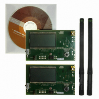
ATAB5423-3-WB
Description
KIT DEMO 315MHZ BLACKBIRD
Manufacturer
Atmel
Type
Transceiver, UHFr
Specifications of ATAB5423-3-WB
Frequency
315MHz
Product
RF Modules
For Use With/related Products
ATA5423
Lead Free Status / RoHS Status
Lead free / RoHS Compliant
Other names
ATAB-5423-3-WB


9.2
62
TX Operation
ATA5423/ATA5425/ATA5428/ATA5429
The transceiver is set to TX operation by using the bits OPM0 and OPM1 in the control
register 1.
Table 9-4.
Before activating TX mode, the TX parameters (bit rate, modulation scheme, etc.) must be
selected as illustrated in
control register 6, Lim_min0 to Lim_min5 in control register 5 and XLIM in control register 4 (see
section
register 4. The FSK frequency deviation is fixed to about ±16 kHz. If P_Mode is set to “1”, the
Manchester modulator is disabled and pattern mode is active (NRZ, see
After the transceiver is set to TX mode, the start-up mode is active and the PLL is enabled. If the
PLL is locked, the TX mode is active.
If the transceiver is in start-up or TX mode, the TX/RX data buffer can be loaded via the 4-wire
serial interface. After the first byte is in the buffer and the TX mode is active, the transceiver
starts transmitting automatically (beginning with the MSB). While transmitting it is always possi-
ble to load new data in the TX/RX data buffer. To prevent a buffer overflow or interruptions
during transmitting, the user must ensure that data is loaded at the same speed as it is
transmitted.
There is a counter that indicates the number of bytes to be transmitted (see section
Configuration” on page
ted, the counter is decremented. The counter value is available via the 4-wire serial interface. An
IRQ is issued if the counter (while counting down) reaches the value defined by the control bits
IR0 and IR1 in control register 1.
Note:
If T_Mode in control register 1 is set to “1”, the transceiver is in TX transparent mode. In this
mode the TX/RX data buffer is disabled and the TX data stream must be applied on pin
SDI_TMDI.
“Control Register” on page
Writing to the control register 1, 4, 5 or 6 during TX mode resets the TX/RX data buffer and the
counter which indicates the number of bytes to be transmitted.
Figure 9-11 on page 63
OPM1
Control Register 1
0
49). If a byte is loaded, the counter is incremented, if a byte is transmit-
Figure 9-11 on page
38). The modulation is selected with ASK/_NFSK in control
illustrates the flow chart of the TX transparent mode.
OPM0
63. The bit rate depends on Baud 0 and Baud 1 in
1
Table 9-5 on page
Function
TX mode
4841D–WIRE–10/07
“Transceiver
65).
Related parts for ATAB5423-3-WB
Image
Part Number
Description
Manufacturer
Datasheet
Request
R

Part Number:
Description:
BOARD BASESTATN UHF RCVR 315MHZ
Manufacturer:
Atmel
Datasheet:

Part Number:
Description:
DEV KIT FOR AVR/AVR32
Manufacturer:
Atmel
Datasheet:

Part Number:
Description:
INTERVAL AND WIPE/WASH WIPER CONTROL IC WITH DELAY
Manufacturer:
ATMEL Corporation
Datasheet:
Part Number:
Description:
Low-Voltage Voice-Switched IC for Hands-Free Operation
Manufacturer:
ATMEL Corporation
Datasheet:
Part Number:
Description:
MONOLITHIC INTEGRATED FEATUREPHONE CIRCUIT
Manufacturer:
ATMEL Corporation
Datasheet:
Part Number:
Description:
AM-FM Receiver IC U4255BM-M
Manufacturer:
ATMEL Corporation
Datasheet:
Part Number:
Description:
Monolithic Integrated Feature Phone Circuit
Manufacturer:
ATMEL Corporation
Datasheet:
Part Number:
Description:
Multistandard Video-IF and Quasi Parallel Sound Processing
Manufacturer:
ATMEL Corporation
Datasheet:
Part Number:
Description:
High-performance EE PLD
Manufacturer:
ATMEL Corporation
Datasheet:
Part Number:
Description:
8-bit Flash Microcontroller
Manufacturer:
ATMEL Corporation
Datasheet:
Part Number:
Description:
2-Wire Serial EEPROM
Manufacturer:
ATMEL Corporation
Datasheet: