ATAB5423-3-WB Atmel, ATAB5423-3-WB Datasheet - Page 47
ATAB5423-3-WB
Manufacturer Part Number
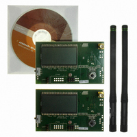
ATAB5423-3-WB
Description
KIT DEMO 315MHZ BLACKBIRD
Manufacturer
Atmel
Type
Transceiver, UHFr
Specifications of ATAB5423-3-WB
Frequency
315MHz
Product
RF Modules
For Use With/related Products
ATA5423
Lead Free Status / RoHS Status
Lead free / RoHS Compliant
Other names
ATAB-5423-3-WB


7.7
7.8
4841D–WIRE–10/07
Low Battery Indicator
Pin VAUX
The status bit Low_Batt is set to “1” if the voltage V
(typically).
Low_Batt is set to “0” if V
serial interface (see
Figure 7-5.
To switch the transceiver from OFF to AUX mode, the voltage V
3.5V (typically) (see
to low, and DVCC and the power supply for external devices VSOUT are switched on.
If V
After the voltage on pin VSOUT exceeds 2.3V (typically) and the start-up time of the XTO is
elapsed, the output clock on pin CLK is available. Because the enabling of pin CLK is asynchro-
nous, the first clock cycle may be incomplete. N_RESET is set to high if V
(typically) and the XTO is settled.
If the transceiver is in any active mode (IDLE, TX, RX, RX_Polling), a positive edge on pin VAUX
and V
an interrupt. If P_On_Aux is still “1” during the positive edge on pin VAUX no interrupt is issued.
P_On_Aux and the interrupt are deleted after reading the status register.
VAUX
VAUX
exceeds 3.5V (typically) the status bit P_On_Aux is set to “1” and an interrupt is issued.
> VS1 + 0.5V sets P_On_Aux to “1”. The state transition P_On_Aux 0
Timing Status Bit Low_Batt
Figure 5-3 on page
Figure 7-6 on page
ATA5423/ATA5425/ATA5428/ATA5429
VSOUT
exceeds V
V
Read Status Register
IDLE, AUX, TX, RX
VSOUT
RX Polling Mode
34).
48). If V
Low_Batt = 1
Thres_2
< 2.38V (typ)
or
?
Y
VAUX
and the status register is read via the 4-wire
exceeds 2V (typically) pin N_RESET is set
VSOUT
N
on pin VSOUT drops below 2.38V
VAUX
on pin VAUX must exceed
VSOUT
exceeds 2.38V
1 generates
47
Related parts for ATAB5423-3-WB
Image
Part Number
Description
Manufacturer
Datasheet
Request
R

Part Number:
Description:
BOARD BASESTATN UHF RCVR 315MHZ
Manufacturer:
Atmel
Datasheet:

Part Number:
Description:
DEV KIT FOR AVR/AVR32
Manufacturer:
Atmel
Datasheet:

Part Number:
Description:
INTERVAL AND WIPE/WASH WIPER CONTROL IC WITH DELAY
Manufacturer:
ATMEL Corporation
Datasheet:
Part Number:
Description:
Low-Voltage Voice-Switched IC for Hands-Free Operation
Manufacturer:
ATMEL Corporation
Datasheet:
Part Number:
Description:
MONOLITHIC INTEGRATED FEATUREPHONE CIRCUIT
Manufacturer:
ATMEL Corporation
Datasheet:
Part Number:
Description:
AM-FM Receiver IC U4255BM-M
Manufacturer:
ATMEL Corporation
Datasheet:
Part Number:
Description:
Monolithic Integrated Feature Phone Circuit
Manufacturer:
ATMEL Corporation
Datasheet:
Part Number:
Description:
Multistandard Video-IF and Quasi Parallel Sound Processing
Manufacturer:
ATMEL Corporation
Datasheet:
Part Number:
Description:
High-performance EE PLD
Manufacturer:
ATMEL Corporation
Datasheet:
Part Number:
Description:
8-bit Flash Microcontroller
Manufacturer:
ATMEL Corporation
Datasheet:
Part Number:
Description:
2-Wire Serial EEPROM
Manufacturer:
ATMEL Corporation
Datasheet: