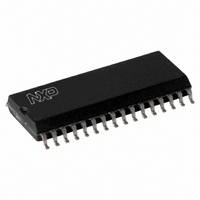
CLRC63201T/0FE,112 NXP Semiconductors, CLRC63201T/0FE,112 Datasheet - Page 37

CLRC63201T/0FE,112
Manufacturer Part Number
CLRC63201T/0FE,112
Description
IC I.CODE HS READER 32-SOIC
Manufacturer
NXP Semiconductors
Series
I-Coder
Specifications of CLRC63201T/0FE,112
Rf Type
Read Only
Frequency
13.56MHz
Features
ISO14443-A, ISO14443-B, ISO15693, ISO18000-3
Package / Case
32-SOIC (0.300", 7.50mm Width)
Product
RFID Readers
Operating Temperature Range
- 25 C to + 85 C
Lead Free Status / RoHS Status
Lead free / RoHS Compliant
Lead Free Status / RoHS Status
Lead free / RoHS Compliant, Lead free / RoHS Compliant
Other names
568-2199-5
935269690112
CLRC632
CLRC63201TD
935269690112
CLRC632
CLRC63201TD
Available stocks
Company
Part Number
Manufacturer
Quantity
Price
Company:
Part Number:
CLRC63201T/0FE,112
Manufacturer:
IR
Quantity:
3 400
Part Number:
CLRC63201T/0FE,112
Manufacturer:
NXP/恩智浦
Quantity:
20 000
NXP Semiconductors
CLRC632_35
Product data sheet
PUBLIC
9.10.2.3 Correlation circuitry
9.10.2.4 Evaluation and digitizer circuitry
9.11 Serial signal switch
The correlation circuitry calculates the degree of matching between the received and an
expected signal. The output is a measure of the amplitude of the expected signal in the
received signal. This is done for both, the Q and I-channels. The correlator provides two
outputs for each of the two input channels, resulting in a total of four output signals.
The correlation circuitry needs the phase information for the incoming card signal for
optimum performance. This information is defined for the microprocessor using the
BitPhase register. This value defines the phase relationship between the transmitter and
receiver clock in multiples of the BitPhase time (t
The correlation results are evaluated for each bit-half of the Manchester coded signal. The
evaluation and digitizer circuit decides from the signal strengths of both bit-halves, if the
current bit is valid
Select the following levels for optimal using RxThreshold register bits:
After data transmission, the card is not allowed to send its response before a preset time
period which is called the frame guard time in the ISO/IEC 14443 standard. The length of
this time period is set using the RxWait register’s RxWait[7:0] bits. The RxWait register
defines when the receiver is switched on after data transmission to the card in multiples of
one bit duration.
If bit RcvClkSelI is set to logic 1, the I-clock is used to clock the correlator and evaluation
circuits. If bit RcvClkSelI is set to logic 0, the Q-clock is used.
Remark: It is recommended to use the Q-clock.
The CLRC632 comprises two main blocks:
The interface between these two blocks can be configured so that the interface signals are
routed to pins MFIN and MFOUT. This makes it possible to connect the analog part of one
CLRC632 to the digital part of another device.
The serial signal switch can be used to measure MIFARE and ISO/IEC 14443 A as well as
related I-CODE1 and ISO/IEC 15693 signals.
•
•
•
•
•
•
If the bit is valid, its value is identified
If the bit is not valid, it is checked to identify if it contains a bit-collision
MinLevel[3:0]: defines the minimum signal strength of the stronger bit-halve’s signal
which is considered valid.
CollLevel[3:0]: defines the minimum signal strength relative to the amplitude of the
stronger half-bit that has to be exceeded by the weaker half-bit of the Manchester
coded signal to generate a bit-collision. If the signal’s strength is below this value,
logic 1 and logic 0 can be determined unequivocally.
digital circuitry: comprising the state machines, encoder and decoder logic etc.
analog circuitry: comprising the modulator, antenna drivers, receiver and
amplification circuitry
Rev. 3.5 — 10 November 2009
Multiple protocol contactless reader IC (MIFARE/I-CODE1)
073935
BitPhase
) = 1 / 13.56 MHz.
CLRC632
© NXP B.V. 2009. All rights reserved.
37 of 126


