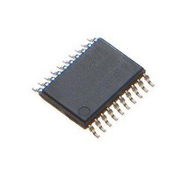
MCP4441T-503E/ST Microchip Technology, MCP4441T-503E/ST Datasheet - Page 71

MCP4441T-503E/ST
Manufacturer Part Number
MCP4441T-503E/ST
Description
IC DGTL POT 129TAPS QUAD 20TSSOP
Manufacturer
Microchip Technology
Datasheet
1.MCP4441-103EML.pdf
(100 pages)
Specifications of MCP4441T-503E/ST
Package / Case
20-TSSOP (0.173", 4.40mm Width)
Temperature Coefficient
150 ppm/°C Typical
Taps
129
Resistance (ohms)
50K
Number Of Circuits
4
Memory Type
Non-Volatile
Interface
I²C, 2-Wire Serial
Voltage - Supply
2.7 V ~ 5.5 V
Operating Temperature
-40°C ~ 125°C
Mounting Type
Surface Mount
Number Of Pots
Quad
Taps Per Pot
129
Resistance
50 KOhms
Wiper Memory
Non Volatile
Buffered Wiper
Buffered
Digital Interface
I2C
Operating Supply Voltage
2.7 V to 5.5 V
Supply Current
600 uA
Maximum Operating Temperature
+ 125 C
Minimum Operating Temperature
- 40 C
Description/function
Quad I2C Digital POT with Nonvolatile Memory
Mounting Style
SMD/SMT
Supply Voltage (max)
5.5 V
Supply Voltage (min)
2.7 V
Lead Free Status / RoHS Status
Lead free / RoHS Compliant
Available stocks
Company
Part Number
Manufacturer
Quantity
Price
Part Number:
MCP4441T-503E/ST
Manufacturer:
MICROCHIP/微芯
Quantity:
20 000
7.8
These commands are special cases of the High
Voltage
Increment Wiper
memory locations 02h, 03h, 08h, 09h, and 0Fh. This
command is used to enable or disable either the
software Write Protect, wiper 0 WiperLock Technology,
wiper 1 WiperLock Technology, wiper 2 WiperLock
Technology, or wiper 3 WiperLock Technology.
6
command and the result of those commands on the
nonvolatile WP, WL0, or WL1 bits.
TABLE 7-6:
© 2010 Microchip Technology Inc.
Note 1:
shows the memory addresses, the High Voltage
0Bh - 0Eh
Address
Memory
0Ah
04h
05h
00h
01h
02h
03h
06h
07h
08h
09h
0Fh
Modify Write Protect or WiperLock
Technology (High Voltage)
Decrement Wiper
Enable and Disable
(1)
(1)
(1)
Reserved addresses: Increment or Decrement commands are invalid for these addresses.
(1)
ADDRESS MAP TO MODIFY WRITE PROTECT AND WIPERLOCK TECHNOLOGY
High Voltage
Wiper 0 register is decremented
Wiper 1 register is decremented
WL0 is enabled
WL1 is enabled
TCON0 register not changed
STATUS register not changed
Wiper 2 register is decremented
Wiper 3 register is decremented
WL2 is enabled
WL3 is enabled
TCON1 register not changed
Reserved
WP is enabled
commands to the nonvolatile
and the High Voltage
Decrement Wiper
Table 7-
Commands and Results
7.8.1
Figure 7-9
the formats for a single Modify Write Protect or
Wiper-Lock Technology command.
A Modify Write Protect or WiperLock Technology
Command will only start an EEPROM write cycle (t
after a properly formatted Command has been
received and the Stop condition occurs.
During an EEPROM write cycle, only serial commands
to Volatile memory (addresses 00h, 01h, 04h, and 05h)
are accepted. All other serial commands are ignored
until the EEPROM write cycle (t
allows the Host Controller to operate on the Volatile
Wiper registers and the TCON register, and to Read
the Status Register. The EEWA bit in the Status register
indicates the status of an EEPROM Write Cycle.
High Voltage
Wiper 0 register is incremented
Wiper 1 register is incremented
WL0 is disabled
WL1 is disabled
TCON0 register not changed
STATUS register not changed
Wiper 2 register is incremented
Wiper 3 register is incremented
WL2 is disabled
WL3 is disabled
TCON1 register not changed
Reserved
WP is disabled
(Disable) and
SINGLE MODIFY (ENABLE OR
DISABLE) WRITE PROTECT OR
WIPERLOCK TECHNOLOGY (HIGH
VOLTAGE)
MCP444X/446X
Increment Wiper
Figure 7-10
wc
) completes. This
DS22265A-page 71
(Enable) show
wc
)


