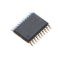
MCP4441T-503E/ST Microchip Technology, MCP4441T-503E/ST Datasheet - Page 91

MCP4441T-503E/ST
Manufacturer Part Number
MCP4441T-503E/ST
Description
IC DGTL POT 129TAPS QUAD 20TSSOP
Manufacturer
Microchip Technology
Datasheet
1.MCP4441-103EML.pdf
(100 pages)
Specifications of MCP4441T-503E/ST
Package / Case
20-TSSOP (0.173", 4.40mm Width)
Temperature Coefficient
150 ppm/°C Typical
Taps
129
Resistance (ohms)
50K
Number Of Circuits
4
Memory Type
Non-Volatile
Interface
I²C, 2-Wire Serial
Voltage - Supply
2.7 V ~ 5.5 V
Operating Temperature
-40°C ~ 125°C
Mounting Type
Surface Mount
Number Of Pots
Quad
Taps Per Pot
129
Resistance
50 KOhms
Wiper Memory
Non Volatile
Buffered Wiper
Buffered
Digital Interface
I2C
Operating Supply Voltage
2.7 V to 5.5 V
Supply Current
600 uA
Maximum Operating Temperature
+ 125 C
Minimum Operating Temperature
- 40 C
Description/function
Quad I2C Digital POT with Nonvolatile Memory
Mounting Style
SMD/SMT
Supply Voltage (max)
5.5 V
Supply Voltage (min)
2.7 V
Lead Free Status / RoHS Status
Lead free / RoHS Compliant
Available stocks
Company
Part Number
Manufacturer
Quantity
Price
Part Number:
MCP4441T-503E/ST
Manufacturer:
MICROCHIP/微芯
Quantity:
20 000
APPENDIX B:
Some designers may want to understand the device
operational characteristics outside of the specified
operating conditions of the device.
Applications where the knowledge of the resistor
network characteristics could be useful include battery
powered devices and applications that experience
brown-out conditions.
In battery applications, the application voltage decays
over time until new batteries are installed. As the
voltage decays, the system will continue to operate. At
some voltage level, the application will be below its
specified operating voltage range. This is dependent
on the individual components used in the design. It is
still useful to understand the device characteristics to
expect when this low-voltage range is encountered.
Unlike a microcontroller, which can use an external
supervisor device to force the controller into the Reset
state, a digital potentiometer’s resistance characteristic
is not specified. But understanding the operational
characteristics can be important in the design of the
applications circuit for this low-voltage condition.
Other
understanding the low-voltage characteristics of the
resistor network could be important is for system brown
out conditions.
For the MCP444X/446X devices, the analog operation
is specified at a minimum of 2.7V. Device testing has
Terminal A connected to the device V
potentiometer configuration only) and Terminal B
connected to V
© 2010 Microchip Technology Inc.
application
SS
.
CHARACTERIZATION
DATA ANALYSIS
system
scenarios
DD
(for the
where
B.1
This
semiconductor characteristics at lower voltages. This is
important
characterization graphs of the MCP444X/446X devices
can be better understood.
For this discussion, we will use the 5 kΩ device data.
This data was chosen since the variations of wiper
resistance have much greater implications for devices
with smaller R
Figure B-1
average R
the R
Non-linear behavior occurs at approximately wiper
code 160. This is better shown in
R
change is due to the change in the wiper resistance.
FIGURE B-1:
from Average R
and Temperature (V
FIGURE B-2:
Temperature (V
BW
7000
6000
5000
4000
3000
2000
1000
resistance changes from a linear slope. This
-1.00%
-2.00%
-3.00%
-4.00%
-5.00%
-6.00%
-7.00%
BW
2.00%
1.00%
0.00%
appendix
0
Low-Voltage Operation
0
BW
resistance versus the wiper code graph.
0
shows the worst case R
so
as a percentage, while
32
AB
MCP444X/446X
32
that
resistances.
BW
DD
gives
64
64
= 1.8V, I
(R
DD
1.8V Worst Case R
R
the
BW0
96
BW
96
Wiper Code
= 1.8V, I
an
Wiper Code
-R
vs. Wiper Code And
128
1.8V
128
W
BW3
overview
Figure
= 190
160
160
W
) vs. Wiper Code
resistor
BW
DS22265A-page 91
Figure B-2
= 190
192
192
B-2, where the
µ
error from the
A).
of
-40C
+25C
+85C
+125C
224
224
BW
-40C
+25C
+85C
+125C
µ
A).
network
CMOS
shows
Error
256
256


