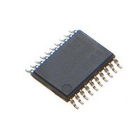
MCP4441T-503E/ST Microchip Technology, MCP4441T-503E/ST Datasheet - Page 76

MCP4441T-503E/ST
Manufacturer Part Number
MCP4441T-503E/ST
Description
IC DGTL POT 129TAPS QUAD 20TSSOP
Manufacturer
Microchip Technology
Datasheet
1.MCP4441-103EML.pdf
(100 pages)
Specifications of MCP4441T-503E/ST
Package / Case
20-TSSOP (0.173", 4.40mm Width)
Temperature Coefficient
150 ppm/°C Typical
Taps
129
Resistance (ohms)
50K
Number Of Circuits
4
Memory Type
Non-Volatile
Interface
I²C, 2-Wire Serial
Voltage - Supply
2.7 V ~ 5.5 V
Operating Temperature
-40°C ~ 125°C
Mounting Type
Surface Mount
Number Of Pots
Quad
Taps Per Pot
129
Resistance
50 KOhms
Wiper Memory
Non Volatile
Buffered Wiper
Buffered
Digital Interface
I2C
Operating Supply Voltage
2.7 V to 5.5 V
Supply Current
600 uA
Maximum Operating Temperature
+ 125 C
Minimum Operating Temperature
- 40 C
Description/function
Quad I2C Digital POT with Nonvolatile Memory
Mounting Style
SMD/SMT
Supply Voltage (max)
5.5 V
Supply Voltage (min)
2.7 V
Lead Free Status / RoHS Status
Lead free / RoHS Compliant
Available stocks
Company
Part Number
Manufacturer
Quantity
Price
Part Number:
MCP4441T-503E/ST
Manufacturer:
MICROCHIP/微芯
Quantity:
20 000
MCP444X/446X
8.5
In audio volume control applications, the use of
logarithmic steps is desirable since the human ear
hears in a logarithmic manner. The use of a linear
potentiometer can approximate a log potentiometer,
but with fewer steps. An 8-bit potentiometer can
achieve fourteen 3 dB log steps plus a 100% (0 dB)
and a mute setting.
Figure 8-7
MCP44x1 resistor networks being used to attenuate an
input signal. In this case, the attenuation will be ground
referenced. Terminal B can be connected to a common
mode voltage, but the voltages on the A, B and Wiper
terminals must not exceed the MCP44x1’s V
voltage limits.
FIGURE 8-7:
Diagram - Ground Referenced.
Equation 8-1
dB gain ratios for the digital potentiometer, while
Equation 8-2
resistance dB gain ratios. These two equations assume
that the B terminal is connected to ground.
If terminal B is not directly resistively connected to
ground, then this terminal B to ground resistance
(R
Equation 8-3
DS22265A-page 76
B2GND
) must be included into the calculation.
Implementing Log Steps with a
Linear Digital Potentiometer
shows a block diagram of one of the
shows this equation.
shows the equation to calculate voltage
shows
P0A
MCP44X1
Signal Attenuation Block
the
P0B
P0W
equation
to
calculate
DD
/V
SS
EQUATION 8-1:
EQUATION 8-2:
EQUATION 8-3:
Table 8-1
digital potentiometers to implement the log attenuation.
The table shows the wiper codes for -3 dB, -2 dB, and
-1 dB attenuation steps. This table also shows the
calculated attenuation based on the wiper code’s linear
step. Calculated attenuation values less than the
desired attenuation are shown with
wiper code values, the attenuation may skip a step, if
this occurs the next attenuation value is colored
magenta
in the -3 dB column the -48 dB value is highlighted
since the -45 dB step could not be implemented (there
are no wiper codes between 2 and 1).
Terminal B connected to Ground (see
Terminal B through R
L = 20 * log
L = 20 * log
to highlight that a skip occurred. For example,
shows the codes that can be used for 8-bit
10
10
L = 20 * log
dB
-3
-2
-1
(R
( (R
BW
BW
B2GND
/ R
dB CALCULATIONS
(VOLTAGE)
dB CALCULATIONS
(RESISTANCE) - CASE 1
dB CALCULATIONS
(RESISTANCE) - CASE 2
V
+ R
© 2010 Microchip Technology Inc.
OUT
AB
10
0.70795
0.79433
0.89125
B2GND
)
(V
to Ground
/ V
OUT
IN
) / (R
Ratio
/ V
red
IN
Figure
AB
)
text. At lower
+ R
B2GND
8-7)
) )


