LC1D18R7 SQUARE D, LC1D18R7 Datasheet - Page 141
LC1D18R7
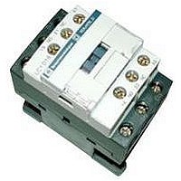
Manufacturer Part Number
LC1D18R7
Description
IEC Contactor
Manufacturer
SQUARE D
Datasheet
1.LC1D09BD.pdf
(252 pages)
Specifications of LC1D18R7
No. Of Poles
3
Contact Configuration
3PST-NO
Relay Mounting
DIN Rail
Coil Voltage Vac Nom
440V
Relay Terminals
Screw Clamp
Width
45mm
Coil Resistance
2.24kohm
Nom Operating Power
10kW
External Width
45mm
Operating Voltage
600VAC
Switching Power Ac1
3hp
Switching Power Ac3
15hp
Switching Current Ac1
32A
Switching Current Ac3
18A
Load Current Inductive
18A
Load Current Resistive
32A
Rohs Compliant
Yes
Lead Free Status / RoHS Status
Lead free / RoHS Compliant


01/04
Capacitor-switching Contactors (International Applications Only)
For Switching 3-phase Capacitor Banks used for Power Factor Correction - Selection
(1)
Standard Contactors
Capacitors, together with the circuits to which they are connected, form oscillatory circuits which can, at the moment of switch-on, give rise to high
transient currents (> 180 In) at high frequencies (1 to 15 kHz).
As a general rule, the peak current on energizing is lower when:
- the mains inductances are high,
- the line transformer ratings are low,
- the transformer short-circuit voltage is high,
- the ratio between the sum of the ratings of the capacitors already switched into the circuit and that of the capacitors to be switched in is small (for multiple
In accordance with standards IEC 60070, NF C 54-100, VDE 0560, the switching contactor must be able to withstand a continuous current of 1.43 times
the rated current of the capacitor bank step being switched.
The rated operational powers given in the tables opposite take this overload into account.
Short-circuit protection is normally provided by gL type HPC fuses rated at 1.7 to 2 In.
Contactor Applications
Operating Conditions
Capacitors are directly switched. The values of peak current at switch-on must not exceed the values indicated opposite.
An inductor may be inserted in each of the three phases supplying the capacitors to reduce the peak current, if necessary. Inductance values are
determined according to the selected operating temperature.
Power factor correction by a single-step capacitor bank
The use of a choke inductor is unnecessary; the inductance of the mains supply is adequate to limit the peak to a value compatible with the contactor
characteristics.
Power factor correction by a multiple-step capacitor bank
Select a special contactor as defined on page 142.
If a standard contactor is used, it is essential to insert a choke inductor in each of the three phases of each step.
Maximum operational power of contactors
Standard Contactors
Maximum operating rate: 120 operating cycles/hour.
Electrical durability at maximum load: 100,000 operating cycles.
With choke inductors connected, where necessary.
Operational power at 50/60 Hz
220 V
240 V
kVAR
6
9
11
14
17
22
22
35
50
60
70
80
90
100
125
180
250
250
step capacitor banks).
Upper limit of temperature category conforming to IEC 70.
40 °C / 104 °F (1)
400 V
440 V
kVAR
11
15
20
25
30
40
40
60
90
110
125
140
160
190
220
300
400
400
Capacitor-switching Contactors (International Applications Only)
600 V
690 V
kVAR
15
20
25
30
37
50
50
75
125
135
160
190
225
275
300
400
600
600
220 V
240 V
kVAR
6
9
11
14
17
22
22
35
38
40
50
60
75
85
100
125
190
190
55 °C / 131 °F (1)
400 V
440 V
kVAR
11
15
20
25
30
40
40
60
75
85
100
110
125
140
160
220
350
350
©
2001-2004 Schneider Electric All Rights Reserved
600 V
690 V
kVAR
15
20
25
30
37
50
50
75
80
90
100
110
125
165
200
300
500
500
Maximum Peak
Current
A
560
850
1600
1900
2160
2160
3040
3040
3100
3300
3500
4000
5000
6500
8000
10 000
12 000
14 200
Contactor Size
LC1D09, D12
LC1D18
LC1D25
LC1D32, D38
LC1D40
LC1D50
LC1D65
LC1D80, D95
LC1D115
LC1D150
LC1F185
LC1F225
LC1F265
LC1F330
LC1F400
LC1F500
LC1F630
LC1F800
141
Related parts for LC1D18R7
Image
Part Number
Description
Manufacturer
Datasheet
Request
R


Part Number:
Description:
Pushbutton, Non-Illum'd Red "STOP", Momentary, 1NO-1NC, Square 30mm, 10A, 600V
Manufacturer:
SQUARE D
Datasheet:

Part Number:
Description:
KITS,TWIDO? PROGRAMMABLE CONTROLLERS,KITS,TWIDOPACK STARTER KIT - ADVANCED LEVEL,PROGRAMMABLE CONTROLLERS,TWIDO? PROGRAMMABLE CONTROLLERS ,SQUARE D
Manufacturer:
SQUARE D

Part Number:
Description:
LAMPS,INDICATOR,STACKABLE,LAMPS, STACKABLE INDICATOR,VISUAL INDICATING SIGNALS,XVB SERIES INDICATING BANKS ,SQUARE D
Manufacturer:
SQUARE D
Part Number:
Description:
LAMPS,INDICATOR,STACKABLE,LAMPS, STACKABLE INDICATOR,VISUAL INDICATING SIGNALS,XVB SERIES INDICATING BANKS ,SQUARE D
Manufacturer:
SQUARE D
Datasheet:
Part Number:
Description:
I/O EXTENDER MODULE 4 D IN & 2 D OUTPUT
Manufacturer:
SQUARE D
Datasheet:
Part Number:
Description:
CB ACCESSORY, UNDERVOLTAGE TRIP 48V DC
Manufacturer:
SQUARE D
Datasheet: