LC1D18R7 SQUARE D, LC1D18R7 Datasheet - Page 51
LC1D18R7
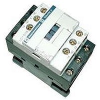
Manufacturer Part Number
LC1D18R7
Description
IEC Contactor
Manufacturer
SQUARE D
Datasheet
1.LC1D09BD.pdf
(252 pages)
Specifications of LC1D18R7
No. Of Poles
3
Contact Configuration
3PST-NO
Relay Mounting
DIN Rail
Coil Voltage Vac Nom
440V
Relay Terminals
Screw Clamp
Width
45mm
Coil Resistance
2.24kohm
Nom Operating Power
10kW
External Width
45mm
Operating Voltage
600VAC
Switching Power Ac1
3hp
Switching Power Ac3
15hp
Switching Current Ac1
32A
Switching Current Ac3
18A
Load Current Inductive
18A
Load Current Resistive
32A
Rohs Compliant
Yes
Lead Free Status / RoHS Status
Lead free / RoHS Compliant


01/04
LC2K09004
LC8K09105
Selection of Reversing Contactors for Resistive Loads
Three- and Four-Pole Contactors for AC Control Circuits
The tables below show general purpose and sensitive-environment three-pole reversing and four-pole
change over contactors for AC control circuits. The sensitive-environment contactors are recommended
for use in areas sensitive to noise, high interference mains supplies, and so forth. The contactors
incorporate an integrated mechanical interlock.
Both types of contactors mount on 35 mm DIN rails or with 4 mm (# 6) screws. The wire termination
screws are in the open, “ready-to-tighten” position. In addition, the sensitive-environment contactors
include a coil with a built-in rectifier and suppressor. Customer wiring is required to connect coil
terminations to the electrical interlock; see page 60 (top row, center wiring diagram).
For information on add-on auxiliary contact blocks and accessories, see page 54 to 58.
General-Purpose Contactors
Sensitive-Environment Contactors
Non-inductive
loads Category
AC-1 Maximum
current at
(122 °F)
A
20
20
f For mains supplies with a high level of interference (voltage surge > 800 V), use a suppressor module LA4KE1FC (50 to 129 V) or
p Use voltage codes on page 52 “Voltage Code Table” to complete catalog number.
q Pre-wired power circuit connections are standard on screw clamp versions.
LAFKE1UG (130 to 250 V), see page 56.
50 °C
Type of Connection
Screw clamp
Slip-on 1 x 0.25 in. or 2 x 0.11 in.
Solder pins for circuit board
Spring terminals
Screw clamp
Slip-on 1 x 0.25 in. or 2 x 0.11 in.
Solder pins for circuit board
q
q
f
Power
Poles
N.O.
3
3
4
3
3
4
3
3
4
3
3
4
3
3
4
3
3
4
3
3
4
Selection of Contactors for Resistive Loads
N.C.
–
–
–
–
–
–
–
–
–
–
–
–
–
–
–
–
–
–
–
–
–
Auxiliary
Contacts
N.O.
1
–
–
–
1
–
1
–
–
1
–
–
1
–
–
–
1
–
1
–
–
N.C.
–
1
–
1
–
–
1
–
–
1
–
–
–
1
–
1
–
–
1
–
–
©
2001-2004 Schneider Electric All Rights Reserved
LC2K0910
LC2K0901
LC2K09004
LC2K09107
LC2K09017
LC2K090047
LC2K09105
LC2K09015
LC2K090045
LC2K09103
LC2K09013
LC2K090043
LC8K0910
LC8K0901
LC8K09004
LC8K09107
LC8K09017
LC8K090047
LC8K09105
LC8K09015
LC8K090045
Catalog
Number
f
f
p
Weight lb. (kg)
0.86 (0.390)
0.86 (0.390)
0.84 (0.380)
0.81 (0.370)
0.81 (0.370)
0.81 (0.370)
0.95 (0.430)
0.95 (0.430)
0.95 (0.430)
0.86 (0.390)
0.86 (0.390)
0.86 (0.390)
1.05 (0.480)
1.05 (0.480)
1.03 (0.470)
1.01 (0.460)
1.01 (0.460)
1.01 (0.460)
1.14 (0.520)
1.14 (0.520)
1.14 (0.520)
51
Related parts for LC1D18R7
Image
Part Number
Description
Manufacturer
Datasheet
Request
R


Part Number:
Description:
Pushbutton, Non-Illum'd Red "STOP", Momentary, 1NO-1NC, Square 30mm, 10A, 600V
Manufacturer:
SQUARE D
Datasheet:

Part Number:
Description:
KITS,TWIDO? PROGRAMMABLE CONTROLLERS,KITS,TWIDOPACK STARTER KIT - ADVANCED LEVEL,PROGRAMMABLE CONTROLLERS,TWIDO? PROGRAMMABLE CONTROLLERS ,SQUARE D
Manufacturer:
SQUARE D

Part Number:
Description:
LAMPS,INDICATOR,STACKABLE,LAMPS, STACKABLE INDICATOR,VISUAL INDICATING SIGNALS,XVB SERIES INDICATING BANKS ,SQUARE D
Manufacturer:
SQUARE D
Part Number:
Description:
LAMPS,INDICATOR,STACKABLE,LAMPS, STACKABLE INDICATOR,VISUAL INDICATING SIGNALS,XVB SERIES INDICATING BANKS ,SQUARE D
Manufacturer:
SQUARE D
Datasheet:
Part Number:
Description:
I/O EXTENDER MODULE 4 D IN & 2 D OUTPUT
Manufacturer:
SQUARE D
Datasheet:
Part Number:
Description:
CB ACCESSORY, UNDERVOLTAGE TRIP 48V DC
Manufacturer:
SQUARE D
Datasheet: