LC1D18R7 SQUARE D, LC1D18R7 Datasheet - Page 185
LC1D18R7
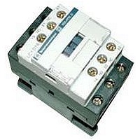
Manufacturer Part Number
LC1D18R7
Description
IEC Contactor
Manufacturer
SQUARE D
Datasheet
1.LC1D09BD.pdf
(252 pages)
Specifications of LC1D18R7
No. Of Poles
3
Contact Configuration
3PST-NO
Relay Mounting
DIN Rail
Coil Voltage Vac Nom
440V
Relay Terminals
Screw Clamp
Width
45mm
Coil Resistance
2.24kohm
Nom Operating Power
10kW
External Width
45mm
Operating Voltage
600VAC
Switching Power Ac1
3hp
Switching Power Ac3
15hp
Switching Current Ac1
32A
Switching Current Ac3
18A
Load Current Inductive
18A
Load Current Resistive
32A
Rohs Compliant
Yes
Lead Free Status / RoHS Status
Lead free / RoHS Compliant


01/04
Type
Control Circuit Characteristics (LX1/LX8 type coils)
Rated control circuit voltage (Vc)
Control voltage limits
(
Average consumption
at 20 °C (68 °F) and at Vc
Heat dissipation
Operating time c
Mechanical durability to Vc
in millions of operating cycles
Maximum operating rate at ambient
temperature
Cabling
Tightening torque
Mechanical latching
c
55 °C [131 °F])
The closing time “C” is measured from the moment the coil supply is switched on to initial contact of the main poles.
The opening time “O” is measured from the moment the coil supply is switched off to the moment the main poles separate.
55 °C (131 °F)
50 or 60 Hz
50 or 60 Hz coils
40 to 400 Hz coils
AC 50 Hz
Inrush
AC 50 Hz
Sealed
AC 60 Hz
Inrush
AC 60 Hz
Sealed
Closing “C”
Opening “O”
In operating cycles per hour
Solid or
stranded cable
Stranded cable
without cable end
Stranded cable with
cable end
Solid cable
without cable end
The LA6DK mechanical latch blocks cannot be mounted on LC1F contactors, for similar operation use CR1F magnetic latching contactors (see page 226).
Contactors Type LC1F (115 to 800 A)
Control Circuit: AC Supply
Operational
Drop-out
Operational
Drop-out
50 Hz coil
40 to 400 Hz coil
Power factor
50 Hz coil
40 to 400 Hz coil
Power factor
60 Hz coil
40 to 400 Hz coil
Power factor
60 Hz coil
40 to 400 Hz coil
Power factor
1 or 2 conductors AWG
1 or 2 conductors mm
1 conductor
2 conductors
1 or 2 conductors mm
V
VA
VA
VA
VA
VA
VA
VA
VA
W
ms
ms
mm
mm
N m/lb-in 1.2/10
2
2
2
2
LC1F400
48 to 1000
–
–
0.85 to 1.1 Vc
0.3 to 0.5 Vc
–
1075
0.9
–
15
0.9
–
1075
0.9
–
15
0.9
14
40 to 75
100 to 170
10
Min/max
16/12
Min/max c.s.a.
1/4
1/4
1/2.5
1/4
2400
LC1F500
48 to 1000
–
–
0.85 to 1.1 Vc
0.3 to 0.5 Vc
–
1100
0.9
–
18
0.9
–
1100
0.9
–
18
0.9
18
40 to 75
100 to 170
10
2400
16/12
1/4
1/4
1/2.5
1/4
1.2/10
©
2001-2004 Schneider Electric All Rights Reserved
LC1F630
48 to 1000
–
–
0.85 to 1.1 Vc
0.25 to 0.5 Vc
–
1650
0.9
–
22
0.9
–
1650
0.9
–
22
0.9
20
40 to 80
100 to 200
5
1200
16/12
1/4
1/4
1/2.5
1/4
1.2/10
LC1F780
110 to 500
–
–
0.85 to 1.1 Vc
0.2 to 0.4 Vc
–
2100
0.9
–
50
0.9
–
2100
0.9
–
50
0.9
2 x 22
40 to 80
130 to 230
5
600
16/12
1/4
1/4
1/2.5
1/4
1.2/10
Characteristics
LC1F800
110 to 440
–
–
0.7 to 1.3 Vc
0.3 to 0.5 Vc
–
1300
–
–
15
–
–
1300
–
–
15
–
25
40 to 80
20 to 40
5
600
16/12
1/4
1/4
1/2.5
1/4
1.2/10
185
Related parts for LC1D18R7
Image
Part Number
Description
Manufacturer
Datasheet
Request
R


Part Number:
Description:
Pushbutton, Non-Illum'd Red "STOP", Momentary, 1NO-1NC, Square 30mm, 10A, 600V
Manufacturer:
SQUARE D
Datasheet:

Part Number:
Description:
KITS,TWIDO? PROGRAMMABLE CONTROLLERS,KITS,TWIDOPACK STARTER KIT - ADVANCED LEVEL,PROGRAMMABLE CONTROLLERS,TWIDO? PROGRAMMABLE CONTROLLERS ,SQUARE D
Manufacturer:
SQUARE D

Part Number:
Description:
LAMPS,INDICATOR,STACKABLE,LAMPS, STACKABLE INDICATOR,VISUAL INDICATING SIGNALS,XVB SERIES INDICATING BANKS ,SQUARE D
Manufacturer:
SQUARE D
Part Number:
Description:
LAMPS,INDICATOR,STACKABLE,LAMPS, STACKABLE INDICATOR,VISUAL INDICATING SIGNALS,XVB SERIES INDICATING BANKS ,SQUARE D
Manufacturer:
SQUARE D
Datasheet:
Part Number:
Description:
I/O EXTENDER MODULE 4 D IN & 2 D OUTPUT
Manufacturer:
SQUARE D
Datasheet:
Part Number:
Description:
CB ACCESSORY, UNDERVOLTAGE TRIP 48V DC
Manufacturer:
SQUARE D
Datasheet: