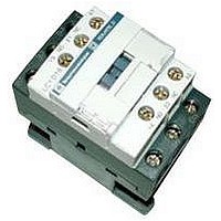
LC1D18R7 SQUARE D, LC1D18R7 Datasheet - Page 17

LC1D18R7
Manufacturer Part Number
LC1D18R7
Description
IEC Contactor
Manufacturer
SQUARE D
Datasheet
1.LC1D09BD.pdf
(252 pages)
Specifications of LC1D18R7
No. Of Poles
3
Contact Configuration
3PST-NO
Relay Mounting
DIN Rail
Coil Voltage Vac Nom
440V
Relay Terminals
Screw Clamp
Width
45mm
Coil Resistance
2.24kohm
Nom Operating Power
10kW
External Width
45mm
Operating Voltage
600VAC
Switching Power Ac1
3hp
Switching Power Ac3
15hp
Switching Current Ac1
32A
Switching Current Ac3
18A
Load Current Inductive
18A
Load Current Resistive
32A
Rohs Compliant
Yes
Lead Free Status / RoHS Status
Lead free / RoHS Compliant
- Current page: 17 of 252
- Download datasheet (14Mb)
01/04
Contactors
AC Supply
Typical Applications
Resistors, non-inductive
or slightly inductive loads
Motors
DC Supply
Typical Applications
Resistors, non inductive or slightly
inductive loads
Shunt wound motors: starting,
counter-current braking, inching
Series wound motors: starting,
counter-current braking, inching
Auxiliary Contacts and Control Relays
AC Supply
Typical Application
Electromagnets
DC Supply
Typical Application
Electromagnets
c
The value 6 P (in watts) is based on practical observations and is considered to represent the majority of magnetic loads up to the maximum limit of P = 50 W, that is 6 P = 300 ms = L/R.
Above this, the loads are made up of smaller loads in parallel. The value 300 ms is therefore a maximum limit whatever the value of current drawn.
Slip ring motors:
starting, breaking
Squirrel cage motors:
starting, breaking while
motor running
Slip ring motors:
starting, plugging, inching
72 VA
72 VA
Utilization
Category
AC-1
AC-2
AC-3
Ie
Ie > 100A
AC-4
Ie
Ie > 100A
Utilization
Category
DC-1
DC-3
DC-5
Utilization
Category
AC-14
AC-15
Utilization
Category
DC-13
The following tables show the results of tests performed according to standard utilization categories
conforming to IEC 60947 based on rated operational current (Ie) and rated operational voltage (Ve).
100A
100A
Making and Breaking Conditions
(normal operation)
Making
I
1 Ie
2 Ie
2 Ie
2 Ie
6 Ie
6 Ie
Making
I
1 Ie
2.5 Ie
2.5 Ie
Making and Breaking Conditions
(normal operation)
Making
I
6 Ie
10 Ie
Making
I
1 Ie
V
1.05 Ve
1.05 Ve
1.05 Ve
1.05 Ve
1.05 Ve
1.05 Ve
V
1 Ve
1.05 Ve
1.05 Ve
V
1 Ve
1 Ve
V
1 Ve
cos
0.8
0.65
0.45
0.35
0.45
0.35
L/R
(ms)
1
2
7.5
cos
0.3
0.3
L/R
(ms)
6 P c
Breaking
I
1 Ie
2 Ie
2 Ie
2 Ie
6 Ie
6 Ie
Breaking
I
1 Ie
2.5 Ie
2.5 Ie
Breaking
I
1 Ie
1 Ie
Breaking
I
1 Ie
V
1.05 Ve
1.05 Ve
1.05 Ve
1.05 Ve
1.05 Ve
1.05 Ve
V
1 Ve
1.05 Ve
1.05 Ve
V
1 Ve
1 Ve
V
1 Ve
cos
0.8
0.65
0.45
0.35
0.45
0.35
L/R
(ms)
1
2
7.5
cos
0.3
0.3
L/R
(ms)
6 P c
Definitions of Utilization Categories
©
Making and Breaking Conditions
(occasional operation)
Making
I
1.5 Ie
4 Ie
10 Ie
10 Ie
12 Ie
12 Ie
Making
I
1.5 Ie
4 Ie
4 Ie
Making and Breaking Conditions
(occasional operation)
Making
I
6 Ie
10 Ie
Making
I
1.1 Ie
2001-2004 Schneider Electric All Rights Reserved
V
1.05 Ve
1.05 Ve
1.05 Ve
1.05 Ve
1.05 Ve
1.05 Ve
V
1.05 Ve
1.05 Ve
1.05 Ve
V
1.1 Ve
1.1 Ve
V
1.1 Ve
cos
0.8
0.65
0.45
0.35
0.35
0.35
L/R
(ms)
1
2.5
15
cos
0.7
0.3
L/R
(ms)
6 P c
Breaking
I
1.5 Ie
4 Ie
8 Ie
8 Ie
10 Ie
10 Ie
Breaking
I
1.5 Ie
4 Ie
4 Ie
Breaking
I
6 Ie
10 Ie
Breaking
I
1 Ie
V
1.05 Ve
1.05 Ve
1.05 Ve
1.05 Ve
1.05 Ve
1.05 Ve
V
1.05 Ve
1.05 Ve
1.05 Ve
V
1.1 Ve
1.1 Ve
V
1.1 Ve
cos
0.8
0.65
0.45
0.35
0.35
0.35
L/R
(ms)
1
2.5
15
cos
0.7
0.3
L/R
(ms)
6 P c
17
Related parts for LC1D18R7
Image
Part Number
Description
Manufacturer
Datasheet
Request
R

Part Number:
Description:
Pushbutton, Non-Illum'd Red "STOP", Momentary, 1NO-1NC, Square 30mm, 10A, 600V
Manufacturer:
SQUARE D
Datasheet:

Part Number:
Description:
KITS,TWIDO? PROGRAMMABLE CONTROLLERS,KITS,TWIDOPACK STARTER KIT - ADVANCED LEVEL,PROGRAMMABLE CONTROLLERS,TWIDO? PROGRAMMABLE CONTROLLERS ,SQUARE D
Manufacturer:
SQUARE D

Part Number:
Description:
LAMPS,INDICATOR,STACKABLE,LAMPS, STACKABLE INDICATOR,VISUAL INDICATING SIGNALS,XVB SERIES INDICATING BANKS ,SQUARE D
Manufacturer:
SQUARE D

Part Number:
Description:
LAMPS,INDICATOR,STACKABLE,LAMPS, STACKABLE INDICATOR,VISUAL INDICATING SIGNALS,XVB SERIES INDICATING BANKS ,SQUARE D
Manufacturer:
SQUARE D
Datasheet:

Part Number:
Description:
I/O EXTENDER MODULE 4 D IN & 2 D OUTPUT
Manufacturer:
SQUARE D
Datasheet:

Part Number:
Description:
CB ACCESSORY, UNDERVOLTAGE TRIP 48V DC
Manufacturer:
SQUARE D
Datasheet:


