LC1D18R7 SQUARE D, LC1D18R7 Datasheet - Page 36
LC1D18R7
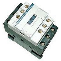
Manufacturer Part Number
LC1D18R7
Description
IEC Contactor
Manufacturer
SQUARE D
Datasheet
1.LC1D09BD.pdf
(252 pages)
Specifications of LC1D18R7
No. Of Poles
3
Contact Configuration
3PST-NO
Relay Mounting
DIN Rail
Coil Voltage Vac Nom
440V
Relay Terminals
Screw Clamp
Width
45mm
Coil Resistance
2.24kohm
Nom Operating Power
10kW
External Width
45mm
Operating Voltage
600VAC
Switching Power Ac1
3hp
Switching Power Ac3
15hp
Switching Current Ac1
32A
Switching Current Ac3
18A
Load Current Inductive
18A
Load Current Resistive
32A
Rohs Compliant
Yes
Lead Free Status / RoHS Status
Lead free / RoHS Compliant


Definitions and Comments
36
Altitude
Ambient air
temperature
Rated operational
current (Ie)
Rated conventional
thermal current (Ith) f
Permissible short
time rating
Rated operational
voltage (Ve)
Rated control circuit
voltage (Vc)
Rated insulation
voltage (Vi)
Rated impulse
withstand voltage
(Vimp)
Rated operational
power (expressed in
kW)
Rated breaking
capacity q
Rated making
capacity q
On-load factor (m)
Pole impedance
Electrical durability
Mechanical durability
f
q
NOTE: These definitions are extracted from standard IEC 60947-1.
Conventional thermal current, in free air, conforming to IEC standards.
For AC applications, the breaking and making capacities are expressed by the rms value of the symmetrical component of the short-circuit current. Taking into account the maximum
asymmetry which may exist in the circuit, the contacts therefore have to withstand a peak asymmetrical current which may be twice the rms symmetrical component.
©
2001-2004 Schneider Electric All Rights Reserved
The low oxygen atmosphere at high altitudes reduces the dielectric strength of the air and hence the rated operational
voltage of the contactor. It also reduces the cooling effect of the air and hence the rated operational current of the
contactor (unless the temperature drops at the same time).
No derating is necessary up to 3000 m (9,840 ft.). Derating factors to be applied above this altitude for main pole
operational voltage and current (AC supply) are as follows.
The temperature of the air surrounding the device, measured near to the device. The operating characteristics are given:
• with no restriction for temperatures between –5 and +55 °C (+23 and +131 °F)
• with restrictions, if necessary, for temperatures between –50 and +70 °C (–58 and +149 °F)
This is defined taking into account the rated operational voltage, operating rate and duty, utilization category and
ambient temperature around the device.
The current which a closed contactor can sustain for a minimum of 8 hours without its temperature rise exceeding the
limits given in the standards.
The current which a closed contactor can sustain for a short time after a period of no load, without dangerous
overheating.
This is the voltage value which, in conjunction with the rated operational current, determines the use of the contactor or
starter, and on which the corresponding tests and the utilization category are based. For three-phase circuits it is
expressed as the voltage between phases. Apart from exceptional cases such as rotor short-circuiting, the rated
operational voltage Ve is less than or equal to the rated insulation voltage Vi.
The rated value of the control circuit voltage, on which the operating characteristics are based. For AC applications, the
values are given for a near sinusoidal wave form (less than 5% total harmonic distortion).
This is the voltage value used to define the insulation characteristics of a device and referred to in dielectric tests
determining leakage paths and creepage distances. As the specifications are not identical for all standards, the rated
value given for each of them is not necessarily the same.
The peak value of a voltage surge which the device is able to withstand without breaking down.
The rated power of the standard motor which can be switched by the contactor, at the stated operational voltage.
This is the current value which the contactor can break in accordance with the breaking conditions specified in the IEC
standard.
This is the current value which the contactor can make in accordance with the making conditions specified in the IEC
standard.
This is the ratio between the time the current flows (t) and the duration of the cycle (T)
Cycle duration: duration of current flow + time at zero current
The impedance of one pole is the sum of the impedance of all the circuit components between the input terminal and
the output terminal. The impedance comprises a resistive component (R) and an inductive component (X=L ). The total
impedance therefore depends on the frequency and is normally given for 50 Hz. This average value is given for the pole
at its rated operational current.
This is the average number of on-load operating cycles which the main pole contacts can perform without maintenance.
The electrical durability depends on the utilization category, the rated operational current and the rated operational
voltage.
This is the average number of on-load operating cycles (i.e. with zero current flow through the main poles) which the
contactor can perform without mechanical failure
m =
Definitions and Comments
T
t
Altitude
Rated operational voltage
Rated operational current
t
T
3500 m
(11,480 ft.)
0.90
0.92
4000 m
(13,120 ft.)
0.80
0.90
4500 m
(14,760 ft.)
0.70
0.88
5000 m
(16,400 ft.)
0.60
0.86
01/04
Related parts for LC1D18R7
Image
Part Number
Description
Manufacturer
Datasheet
Request
R


Part Number:
Description:
Pushbutton, Non-Illum'd Red "STOP", Momentary, 1NO-1NC, Square 30mm, 10A, 600V
Manufacturer:
SQUARE D
Datasheet:

Part Number:
Description:
KITS,TWIDO? PROGRAMMABLE CONTROLLERS,KITS,TWIDOPACK STARTER KIT - ADVANCED LEVEL,PROGRAMMABLE CONTROLLERS,TWIDO? PROGRAMMABLE CONTROLLERS ,SQUARE D
Manufacturer:
SQUARE D

Part Number:
Description:
LAMPS,INDICATOR,STACKABLE,LAMPS, STACKABLE INDICATOR,VISUAL INDICATING SIGNALS,XVB SERIES INDICATING BANKS ,SQUARE D
Manufacturer:
SQUARE D
Part Number:
Description:
LAMPS,INDICATOR,STACKABLE,LAMPS, STACKABLE INDICATOR,VISUAL INDICATING SIGNALS,XVB SERIES INDICATING BANKS ,SQUARE D
Manufacturer:
SQUARE D
Datasheet:
Part Number:
Description:
I/O EXTENDER MODULE 4 D IN & 2 D OUTPUT
Manufacturer:
SQUARE D
Datasheet:
Part Number:
Description:
CB ACCESSORY, UNDERVOLTAGE TRIP 48V DC
Manufacturer:
SQUARE D
Datasheet: