LC1D18R7 SQUARE D, LC1D18R7 Datasheet - Page 142
LC1D18R7
Manufacturer Part Number
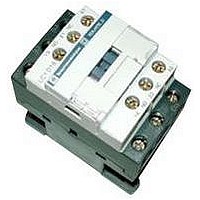
LC1D18R7
Description
IEC Contactor
Manufacturer
SQUARE D
Datasheet
1.LC1D09BD.pdf
(252 pages)
Specifications of LC1D18R7
No. Of Poles
3
Contact Configuration
3PST-NO
Relay Mounting
DIN Rail
Coil Voltage Vac Nom
440V
Relay Terminals
Screw Clamp
Width
45mm
Coil Resistance
2.24kohm
Nom Operating Power
10kW
External Width
45mm
Operating Voltage
600VAC
Switching Power Ac1
3hp
Switching Power Ac3
15hp
Switching Current Ac1
32A
Switching Current Ac3
18A
Load Current Inductive
18A
Load Current Resistive
32A
Rohs Compliant
Yes
Lead Free Status / RoHS Status
Lead free / RoHS Compliant


Capacitor-switching Contactors (International Applications Only)
142
©
LC1DPK12
LC1DFK11
2001-2004 Schneider Electric All Rights Reserved
For Switching 3-phase Capacitor Banks, used for Power Factor Correction
Direct Connection without Choke Inductors - References
Special Contactors
Special contactors LC1DkK are designed for switching 3-phase, single or multiple-step capacitor banks; they conform to standards IEC 60070 and
60831, NFC 54-100, VDE 0560, UL and CSA.
Contactor Applications
Specification
Contactors fitted with a block of early make poles and damping resistors, limiting the value of the current on closing to 60 In max.
This current limitation increases the life of all the components of the installation, in particular that of the fuses and capacitors.
The patented design of the add-on block (No. 90 119-20) ensures safety and long life of the installation.
Operating Conditions
There is no need to use choke inductors for either single or multiple-step capacitor banks.
Short-circuit protection must be provided by gI type fuses rated at 1.7 to 2 In.
Maximum Operational Power
The power values given in the selection table below are for the following operating conditions.
Prospective Peak Current at Switch-on LC1D K
Maximum Operating Rate
Electrical Durability at Nominal Load
Operational Power at 50/60 Hz (1)
220 V
240 V
kVAR
6.7
8.5
10
15
20
25
40
Switching of multiple step capacitor banks (with equal or different power ratings).
The correct contactor for each step is selected from the above table, according to the power rating of the step to be switched.
Example: 50 kVAR 3-step capacitor bank. Temperature 50 °C (122 °F) and U = 400 V or 440 V.
One 25 kVAR step: contactor LC1-DMK, one 15 kVAR step: contactor LC1-DGK and one 10 kVAR step: contactor LC1-DFK.
(1) Operational power of the contactor according to the schematic on page 143.
(2) Standard control circuit voltages.
Volts
50/60 Hz
For other voltages between 24 and 440 V, please consult your Regional Sales Office
(3) The average temperature over a 24-hour period, in accordance with standards IEC 60070 and 60831, is 45 °C (113 °F).
55 °C / 131 °F (3)
B7
24
400 V
440 V
kVAR
12.5
16.7
20
25
33.3
40
60
42
D7
E7
48
LC1DFK, DGK, DLK, DMK, DPK
LC1DTK, DWK
660 V
690 V
kVAR
18
24
30
36
48
58
92
All Contactor Ratings
110
F7
115
FE7
Instantaneous
Auxiliary
Contacts
N.O.
1
–
1
–
1
–
1
–
1
1
1
M7
220
N.C.
1
2
1
2
1
2
1
2
2
2
2
230
P7
400 V
690 V
Tightening
Torque on
Cable End
lb-in (N.m)
11 (1.2)
11 (1.2)
15 (1.7)
15 (1.7)
17 (1.9)
17 (1.9)
22 (2.5)
22 (2.5)
44 (5)
44 (5)
80 (9)
240
U7
Q7
380
200 In
240 operating cycles/hour
100 operating cycles/hour
300,000 operating cycles
200,000 operating cycles
Basic Reference.
Complete with Code
Indicating Control Circuit
Voltage (2)
LC1DFK11
LC1DFK02
LC1DGK11
LC1DGK02
LC1DLK11
LC1DLK02
LC1DMK11
LC1DMK02
LC1DPK12
LC1DTK12
LC1DWK12
400
V7
415
N7
440
R7
Weight lb. (kg)
0.94 (0.430)
0.94 (0.430)
0.99 (0.450)
0.99 (0.450)
1.3 (0.600)
1.3 (0.600)
1.4 (0.630)
1.4 (0.630)
2.9 (1.300)
2.9 (1.300)
3.6 (1.650)
01/04
Related parts for LC1D18R7
Image
Part Number
Description
Manufacturer
Datasheet
Request
R


Part Number:
Description:
Pushbutton, Non-Illum'd Red "STOP", Momentary, 1NO-1NC, Square 30mm, 10A, 600V
Manufacturer:
SQUARE D
Datasheet:

Part Number:
Description:
KITS,TWIDO? PROGRAMMABLE CONTROLLERS,KITS,TWIDOPACK STARTER KIT - ADVANCED LEVEL,PROGRAMMABLE CONTROLLERS,TWIDO? PROGRAMMABLE CONTROLLERS ,SQUARE D
Manufacturer:
SQUARE D

Part Number:
Description:
LAMPS,INDICATOR,STACKABLE,LAMPS, STACKABLE INDICATOR,VISUAL INDICATING SIGNALS,XVB SERIES INDICATING BANKS ,SQUARE D
Manufacturer:
SQUARE D
Part Number:
Description:
LAMPS,INDICATOR,STACKABLE,LAMPS, STACKABLE INDICATOR,VISUAL INDICATING SIGNALS,XVB SERIES INDICATING BANKS ,SQUARE D
Manufacturer:
SQUARE D
Datasheet:
Part Number:
Description:
I/O EXTENDER MODULE 4 D IN & 2 D OUTPUT
Manufacturer:
SQUARE D
Datasheet:
Part Number:
Description:
CB ACCESSORY, UNDERVOLTAGE TRIP 48V DC
Manufacturer:
SQUARE D
Datasheet: