45.150 230V BROYCE CONTROL, 45.150 230V Datasheet
45.150 230V
Manufacturer Part Number
45.150 230V
Description
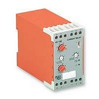
RELAY, UNDER/OVER CURRENT
Manufacturer
BROYCE CONTROL
Datasheet
1.45.150_230V.pdf
(1 pages)
Specifications of 45.150 230V
Contact Configuration
SPCO
Power Consumption
3VA
Supply Voltage Max
230VAC
Contact Current Max
10A
Relay Mounting
DIN Rail
Contact Current Ac Max
10A
Contact Current Dc Max
10A
Adjustment Type
Knob
45150
§
§
§
§
§
§
§
§
-
- Connect the unit as shown in the diagram above.
- Set trip level, hysteresis, delay (from fault) and On delay.
- Select relay mode of operation (See 'timing diagram').
- Apply power (green LED on).
- Current below set trip level:
Troubleshooting
- Check wiring and voltage present.
§ TECHNICAL SPECIFICATION
Supply voltage Un:
(AC: 48 - 63Hz)
Supply variation:
Isolation:
Power consumption:
Monitoring input / range: Y2: 5 - 100mA AC/DC ( 10%)
Hysteresis:
Time delay (t):
Start up delay (t
Reset time:
Ambient temperature:
Relative humidity:
Contact rating:
Electrical life:
Housing:
Weight:
Mounting option:
Terminal conductor
Approvals:
size:
I
BEFORE INSTALLATION, ISOLATE THE SUPPLY
NSTALLATION AND SETTING
Switch = I (red LED on, contacts 15 and 18 closed)
Switch = N (red LED off, contacts 15 and 16 closed)
use of such information shall be entirely at the user's own risk
accurate (subject to change without prior notice); however,
The information provided in this literature is believed to be
OVER CURRENT - ADJUSTABLE TRIP LEVEL
MULTI RANGE
HYSTERESIS - ADJUSTABLE
LATCHING FACILITY - SELECTABLE
DELAY FROM FAULT - ADJUSTABLE
RELAY INVERSION
START UP DELAY - ADJUSTABLE
H+44 (0) 1902 773746 G+44 (0) 1902 420639 Email: sales@broycecontrol.com Web: http://www.broycecontrol.com
Installation work must be carried
out by qualified personnel.
on
):
TIMING DIAGRAM
DIAGRAMME DES TEMPS
ZEITDIAGRAMM
N N
I I
24V, 110V, 230V AC
(Galvanic isolated by transformer)
0.85 - 1.15 x Un
Overvoltage cat. III (IEC 664)
< 3VA
Y3: 0.05 - 1A AC/DC ( 10%)
Y4: 0.5 - 10A AC/DC ( 10%)
5 - 50% (adjustable)
0.1 - 3S ( 20%) (from fault)
0.1 - 10S ( 20%)
-20 to +60 C
+95%
1 x C.O.
AC1 250V AC 10A (2500VA)
AC15 250V AC 6A
DC1 25V DC 10A (250W)
to UL94 VO
to BS5584:1978
(EN50 002, DIN 46277-3)
Conforms to: UL, CUL, CSA,
IEC. CE and
% level
% hyst
200mS
150,000 (AC1)
251g
2 x 1.5mm
2 x 2.5mm
Broyce Control Ltd., Pool Street, Wolverhampton, West Midlands WV2 4HN. England
t
ON
Current Relay
Relais de courant
Strom - Relais
NON-LATCHING MODE
2
2
stranded wire
solid wire
Compliant
t
N
I
% level
% hyst
LATCHING MODE - Y1 and M linked
§
§
§
§
§
§
§
§ MONTAGE ET MISE AU POINT
-
- Branchement comme indiqué dans le diagramme ci-
- Régler le niveau de déplacement, l ' hyteresis et le délai
- Sélectionner le relais du mode d ' opération (voir
- Appliquer la puissance (LED verte allumée).
- Courant sous le niveau de déplacement fixé:
Intervention (pour régler un problème)
- Vérifier les fils et le voltage présent.
§ FICHES TECHNIQUES
Tension d ' alimentation
Variation d ' alimentation: 0.85 - 1.15 x Un
Isolement:
Puissance consommée:
Contrôle de l ' entrée et
du domaine:
Hystérèse:
Délai de temps (t):
Délai de démarrage (t
Temps de remise à zéro:
Température ambiante:
Humidité relative:
Evaluation du contact:
Durée de vie électrique:
Boitier:
Poids:
Option de montage:
Taille du conducteur
Homologations:
Un: (AC: 48 - 63Hz)
terminal:
réserve de changement sans avis préalable) toutefois aux risques et
AVANT MONTAGE, ISOLER L ' ALIMENTATION
dessus.
(de défaillance).
'diagramme de temps').
Les indications contenues dans ce document sont exactes (sous
SOUS-COURANT - NIVEAU DE DÉPLACEMENT
ADJUSTABLE
MULTI-DOMAINES
HYSTERESIS ADJUSTABLE
POSSIBILITÈ DE FERMETURE SÈLECTIONNABLE
DÉLAI DE DÉFAILLANCE ADJUSTABLE
INVERSION DE RELAIS SÉLECTIONNABLE
DÉLAI DE DÉMARRAGE ADJUSTABLE
Interrupteur = I (LED rouge allumeé, contacts 15 et
18 fermés)
Interrupteur = N (LED rouge éteinte, contacts 15 et
16 fermés)
t
menés à bien par le personnel qualifié.
Des travaux d'installation doivent être
latch removed
périls de l ' utilisateur
on
): 0.1 - 10S ( 20%)
24V, 110V, 230V AC
(Protection galvanisée côté
transformateur)
Overvoltage cat. III (IEC 664)
< 3VA
Y2: 5 - 100mA AC/DC ( 10%)
Y3: 0.05 - 1A AC/DC ( 10%)
Y4: 0.5 - 10A AC/DC ( 10%)
5 - 50% (adjustable)
0.1 - 3S ( 20%) (défaillance)
-20 à +60 C
+95%
1 x Inverseur
AC1 250V AC 10A (2500VA)
AC15 250V AC 6A
DC1 25V DC 10A (250W)
à UL94 VO
à BS5584:1978
(EN50 002, DIN 46277-3)
Se conformer à: UL, CUL,
CSA, IEC. CE et
200mS
150,000 (AC1)
251g
2 x 1.5mm
2 x 2.5mm
CONNECTION DIAGRAM
DIAGRAMME DE CONNECTION
SCHALTBILDANSCHLUSS
~
~
Supply
Voltage
2
2
multi-filaire
toron
(n/c contact)
LATCH
across Y1 and M should
Wiring to latch switch
be short as possible
Déférence
A1 15
16 18
Y2 Y3 Y4
Y1 M A2
45150
Monitored
Current
5 - 100mA AC/DC
0.05 - 1A AC/DC
0.5 - 10A AC/DC
§
§
§
§
§
§
§
§ EINBAU UND EINSTELLUNG
-
- Stromversorgung anschliessen wie im Schaltbild unten
- Niveauverschiebung, Hysterese und verzögerung
- Betriebsrelais wählen (siehe 'Zeitdiagramm').
- Energie einleited (LED grün an).
- Strom unter der eigegebener Niveauverschiebung
Störungsbehebung
- Überprüfung von Leitungen und gegenwärtiger
§ TECHNISCHE DATEN
Versorgungsspannung
Wechselversorgung:
Isolation:
Energieverbrauch:
Überwachungseingang /
Hysterese:
Zeitsteuerung (t):
Anlaufzeit (t
Stellzeit:
Umgebungstemperatur:
Allgemeiner
Kontakt Belastung:
Elektrische Lebensdauer:
Gehäuse:
Gewicht:
Befestigungswahl:
Anschlussklemme
Genehmigungen:
Un: (AC: 48 - 63Hz)
Note: Wiring to terminals
bereich:
Feuchtigkeitsgehalt:
/ Kabelgrösse:
monitoring DC currents
M should be as heavy
as possible to prevent
Ensure correct polarity
Y1,Y2, Y3, Y4and
any voltage drops
is observed when
VOR EINBAU DIE STROMVERSORGUNG
ISOLIEREN
angezeigt.
einsetzen (von fehler).
setzen:
Spannung.
Angaben, (Änderungen vorbehalten) jedoch diese Änderungen
LOAD
Es handelt sich in diesen Unterlagen um uns genau bekannte
ÜBERSTROM - NIVEAUVERSCHIEBUNG
VERSTELLBAR
MEHRFACHBEREICH
HYSTERESE - VERSTELLBAR
SPERRVORRICHTUNG - SELEKTIV
FEHLERHAFTE VERZÖGERUNG - EINSTELLBAR
RELAIS INVERSION - SELEKTIV
ANLAUFZEIT - EINSTELLBAR
Schalter = I (LED rot an, Anschlüsse 15 und 18
schliessen)
Schalter = N (LED rot aus, Anschlüsse 15 und 16
schliessen)
Installation Arbeit muß von qualifiziertem
on
laufen auf eigene Gefahr des Benutzers.
):
+ve
-ve
Personal durchgeführt werden.
Width / largeur / Breite. 45 mm
MOUNTING DETAILS
INSTRUCTIONS DE MONTAGE
MONTAGEAUFÜHRUNGEN
Insert screwdriver
to release clip
24V, 110V, 230V AC
(galvanische Isolierung bei
Transformator)
0.85 - 1.15 x Un
Overvoltage cat. III (IEC 664)
< 3VA
Y2: 5 - 100mA AC/DC ( 10%)
Y3: 0.05 - 1A AC/DC ( 10%)
Y4: 0.5 - 10A AC/DC ( 10%)
5 - 50% (verstellbar)
0.1 - 3S ( 20%)
0.1 - 10S ( 20%)
-20 bis +60 C
+95%
1 x Wechsler
AC1 250V AC 10A (2500VA)
AC15 250V AC 6A
DC1 25V DC 10A (250W)
bis UL94 VO
bis BS5584:1978
(EN50 002, DIN 46277-3)
Anmerkung: UL, CUL, CSA,
IEC. CE und
Übereinstimmung
200mS
251g
150,000 (AC1)
2 x 1.5mm
2 x 2.5mm
2
2
Litze
Festdraht
(fehlsteuerung)
78
74
45150-1-B
99
Related parts for 45.150 230V
Image
Part Number
Description
Manufacturer
Datasheet
Request
R

Part Number:
Description:
RELAY, CONDUCTIVE LEVEL CONTROL
Manufacturer:
BROYCE CONTROL
Datasheet:
Part Number:
Description:
RELAY, CONDUCTIVE LEVEL CONTROL, 230VAC
Manufacturer:
BROYCE CONTROL
Datasheet:

Part Number:
Description:
RELAY, THERMISTOR
Manufacturer:
BROYCE CONTROL
Datasheet:

Part Number:
Description:
TEMPERATURE CONTROLLER, PT100
Manufacturer:
BROYCE CONTROL
Datasheet:

Part Number:
Description:
RELAY, MULTIFUNCTION, CURRENT
Manufacturer:
BROYCE CONTROL
Datasheet:
Part Number:
Description:
RELAY, 3PHASE ASYMMETRY, 400VAC
Manufacturer:
BROYCE CONTROL
Datasheet:
Part Number:
Description:
RELAY,EARTH LEAKAGE VARIABLE
Manufacturer:
BROYCE CONTROL
Datasheet:
Part Number:
Description:
RELAY,EARTH LEAKAGE VARIABLE PANEL
Manufacturer:
BROYCE CONTROL
Datasheet:

Part Number:
Description:
RELAY, SEQUENCE/LOSS
Manufacturer:
BROYCE CONTROL
Datasheet:

Part Number:
Description:
RELAY, PHASE SEQUENCE FAILURE
Manufacturer:
BROYCE CONTROL
Datasheet:
Part Number:
Description:
RELAY,SEQUENCE/LOSS, 3PHASE
Manufacturer:
BROYCE CONTROL
Datasheet:

Part Number:
Description:
INDICATOR, 3 PHASE
Manufacturer:
BROYCE CONTROL
Datasheet:

Part Number:
Description:
RELAY, SEQUENCE/LOSS, 3PHASE
Manufacturer:
BROYCE CONTROL
Datasheet:

Part Number:
Description:
RELAY, SEQUENCE/LOSS, 3PHASE
Manufacturer:
BROYCE CONTROL
Datasheet:

Part Number:
Description:
RELAY, LOSS/UNDER/OVER VOLT, 3PHASE
Manufacturer:
BROYCE CONTROL
Datasheet: