45TCR 24/230VAC BROYCE CONTROL, 45TCR 24/230VAC Datasheet
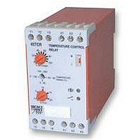
45TCR 24/230VAC
Manufacturer Part Number
45TCR 24/230VAC
Description
TEMPERATURE CONTROLLER, PT100
Manufacturer
BROYCE CONTROL
Datasheet
1.45TCR_24230VAC.pdf
(1 pages)
Specifications of 45TCR 24/230VAC
Thermocouple Type
PT100
Operating Temperature Max
50°C
Operating Temperature Min
-20°C
Output Voltage Max
250VAC
Output Voltage Min
10VDC
Approval Bodies
CE, CSA, C-tick, CUL, IEC, UL
q
q
q
q
q
q
q
Analogue outputs (0 - 10V DC)
Troubleshooting
Type: 45TCR
PT100 Temperature Control Relay
Set point
Telephone: +44 (0) 1902 773746 Facsimile: +44 (0) 1902 420639 Email: sales@broycecontrol.com Web: http://www.broycecontrol.com
The information provided in this literature is believed to be accurate (subject to change without prior notice); however, use of such information shall be entirely at the user’s own risk.
FUNCTION DIAGRAM
INSTALLATION AND SETTING
BEFORE INSTALLATION, ISOLATE THE SUPPLY.
Connect the unit as shown in the diagram below. (Ensure the correct terminals are
used when connecting the supply).
Select the required temperature range. (N.B. fit link between terminals "Y1" and "Z" for
200 to 300 C range)
Set the relay inversion switch to either "N" (Normal) or "I" (Inverted).
Apply power (green LED on).
Connecting between terminals "Y1" and "X1" provides DC voltage relative to the set
point (i.e. set point @ 20% = 2V DC out).
Connecting between terminals "Y1" and "X2" provides DC voltage relative to the
measured temperature within any range selected.
CONNECTION DIAGRAM
2 or 3 wire PT100 input
Monitoring or control of temperature -50 C to 300 C (5 ranges)
Adjustable set point and hysteresis
Relay Operation Inversion switch - Normal/Inverted
Analogue output (0 - 10V DC) relative to set point or measured temperature
Dual voltage supply (AC only)
LED indication of relay, probe and supply status
Check wiring and voltage present.
If the red LED flashes, check PT100 connections
temperature
Relay operation = Normal
de-energised
shown in the
The relay is
condition
Installation work must be carried
Y1 Y2 Y3
15 16 18
115 or 230V
out by qualified personnel.
Broyce Control Ltd., Pool Street, Wolverhampton, West Midlands WV2 4HN. England
PT100
*link
L
X1 X2 Z
A1 A2 A3
Hyst
Hyst
N
24V AC
0 - 10V DC (Relative to set point)
0 - 10V DC (Relative to measured
200 to 300°C range
connect between
For 24V DC only
A1(+) and A2(-)
Fit link* between
Z and Y1 for
temperature
Relay operation = Inverted
temperature)
Supply voltage Un:
Supply variation:
Isolation:
Power consumption:
(@ 115% x Un)
Input:
Temperature ranges: -50 to 50 C, 0 to 50 C, 0 to 100 C,
(selectable)
Set point:
Hysteresis:
Temperature drift:
Time delay:
Ambient temp:
Relative humidity:
Output:
Output rating:
Electrical life:
Analogue output:
Housing:
Weight:
Mounting option:
Terminal conductor
Approvals:
size:
.
TECHNICAL SPECIFICATION
MOUNTING DETAILS
Insert screwdriver
to release clip
W. 45mm
24V DC
24V / 115V AC 45 - 65Hz*
24V / 230V AC 45 - 65Hz*
*Integral transformer
85 - 115% of Un
3.75kV (N.B. There is no isolation between
input and analogue output)
PT100 2 or 3-wire (to DIN 43760)
100 to 200 C, 200 to 300 C
0 - 100% of selected temperature range
0.5 - 20%
0.05%/ C (max.)
200mS (worst case 5 x )
-20 to +50 C
+95%
1 x SPDT
AC 1
AC 15
DC 1
0 - 10V DC (relative to set point or
measured temperature)
I
to UL94 VO
On to 35mm symmetric DIN rail to
BS5584:1978
(EN50 002, DIN 46277-3)
Conforms to UL, CUL, CSA & IEC
CE and
max
1W (27.6V DC)
150,000 ops at rated load
200g
2 x 1.5mm
2 x 2.5mm
4.5VA (27.6V AC), 4.8VA (264V AC)
Dims:
= 2mA R
Compliant
250V AC 8A (2000VA)
250V AC 5A (no), 3A (nc)
25V DC 8A (200W)
2
2
load
stranded wire
solid wire
5K
78
74
Terminal Protection to IP20
99
45TCR-1-B
Related parts for 45TCR 24/230VAC
Image
Part Number
Description
Manufacturer
Datasheet
Request
R

Part Number:
Description:
RELAY, CONDUCTIVE LEVEL CONTROL
Manufacturer:
BROYCE CONTROL
Datasheet:
Part Number:
Description:
RELAY, CONDUCTIVE LEVEL CONTROL, 230VAC
Manufacturer:
BROYCE CONTROL
Datasheet:

Part Number:
Description:
RELAY, THERMISTOR
Manufacturer:
BROYCE CONTROL
Datasheet:

Part Number:
Description:
RELAY, UNDER/OVER CURRENT
Manufacturer:
BROYCE CONTROL
Datasheet:

Part Number:
Description:
RELAY, MULTIFUNCTION, CURRENT
Manufacturer:
BROYCE CONTROL
Datasheet:
Part Number:
Description:
RELAY, 3PHASE ASYMMETRY, 400VAC
Manufacturer:
BROYCE CONTROL
Datasheet:
Part Number:
Description:
RELAY,EARTH LEAKAGE VARIABLE
Manufacturer:
BROYCE CONTROL
Datasheet:
Part Number:
Description:
RELAY,EARTH LEAKAGE VARIABLE PANEL
Manufacturer:
BROYCE CONTROL
Datasheet:

Part Number:
Description:
RELAY, SEQUENCE/LOSS
Manufacturer:
BROYCE CONTROL
Datasheet:

Part Number:
Description:
RELAY, PHASE SEQUENCE FAILURE
Manufacturer:
BROYCE CONTROL
Datasheet:
Part Number:
Description:
RELAY,SEQUENCE/LOSS, 3PHASE
Manufacturer:
BROYCE CONTROL
Datasheet:

Part Number:
Description:
INDICATOR, 3 PHASE
Manufacturer:
BROYCE CONTROL
Datasheet:

Part Number:
Description:
RELAY, SEQUENCE/LOSS, 3PHASE
Manufacturer:
BROYCE CONTROL
Datasheet:

Part Number:
Description:
RELAY, SEQUENCE/LOSS, 3PHASE
Manufacturer:
BROYCE CONTROL
Datasheet:

Part Number:
Description:
RELAY, LOSS/UNDER/OVER VOLT, 3PHASE
Manufacturer:
BROYCE CONTROL
Datasheet: