M1PR BROYCE CONTROL, M1PR Datasheet
M1PR
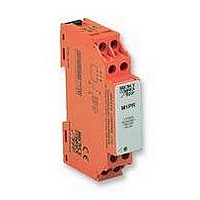
Manufacturer Part Number
M1PR
Description
RELAY, SEQUENCE/LOSS
Manufacturer
BROYCE CONTROL
Datasheet
1.M1PR.pdf
(1 pages)
Specifications of M1PR
Contact Configuration
SPCO
Phase Type
3 Phase
Power Consumption
15VA
Supply Voltage Max
450VAC
Switching Voltage Max
250VAC
Operating Time Range
100ms
Relay Mounting
DIN Rail
Contact Current Ac Max
8A
Contact Current Dc Max
8A
Adjustment Type
Fixed
M1PR
§
§
§
-
- Connect the unit as shown in the diagram above.
- Apply power (red LED on, contacts 15 and 18 closed).
Troubleshooting
- Check wiring and voltage present.
- If incorrect sequence.
- Reverse any 2 phases.
§ TECHNICAL SPECIFICATION
Supply/monitoring
(phase to phase)
Isolation:
Rated impulse withstand
Power consumption:
(450V / 50Hz)
Time delay (t):
Ambient temperature:
Relative humidity:
Contact rating:
Electrical life:
Housing:
Weight:
Mounting option:
Terminal conductor
Approvals:
voltage U:
voltage:
size:
I
BEFORE INSTALLATION, ISOLATE THE SUPPLY
NSTALLATION AND SETTING
use of such information shall be entirely at the user's own risk
accurate (subject to change without prior notice); however,
The information provided in this literature is believed to be
INCORRECT PHASE SEQUENCE /
ROTATION
PHASE FAILURE / LOSS (CLOSED CIRCUIT)
H+44 (0) 1902 773746 G+44 (0) 1902 420639 Email: sales@broycecontrol.com Web: http://www.broycecontrol.com
Installation work must be carried
out by qualified personnel.
TIMING DIAGRAM
DIAGRAMME DES TEMPS
ZEITDIAGRAMM
200 - 450V AC 48 - 63Hz
5.55kV
4kV (1.2/50 S)
< 15VA ( red / yellow phase)
< 0.2VA (blue phase)
-20 to +60 C
+95%
1 x C.O.
AC1 250V AC 8A (2000VA)
AC15 250V AC 5A (no),
3A (nc)
DC1 25V DC 8A (200W)
to UL94 VO
to BS5584:1978
(EN50 002, DIN 46277-3)
Conforms to: UL, CUL, CSA,
IEC. CE and
R(L1)
Y(L2)
B(L3)
100mS (from fault)
150,000 (AC1)
68g
2 x 2.5mm
Broyce Control Ltd., Pool Street, Wolverhampton, West Midlands WV2 4HN. England
Incorrect phase sequence
on connection of supply
Phase Sequence Relay
Relais de séquence de phase
Ablaufphasen Relais
(supply to relay contacts)
B(L3)
Y(L2)
2
solid /stranded
Compliant
t
§
§
§ MONTAGE ET MISE AU POINT
-
- Branchement comme indiqué dans le diagramme ci-
- Appliquer la puissance (LED rouge allumée, contacts 15
Intervention (pour régler un problème)
- Vérifier les fils et le voltage présent.
- Si séquence incorrecte.
- Inverser 2 phases.
§ FICHES TECHNIQUES
Voltage d ' alimentation
(mise en phase)
Isolement:
Impulsion nominale
Puissance consommée:
(450V / 50Hz)
Délai de temps (t):
Température ambiante:
Humidité relative:
Evaluation du contact:
Durée de vie électrique:
Boitier:
Poids:
Option de montage:
Taille du conducteur
Homologations:
Phase loss
contrôlée U:
résistant à la tension:
terminal:
réserve de changement sans avis préalable) toutefois aux risques et
t
AVANT MONTAGE, ISOLER L ' ALIMENTATION
dessus.
et 18 fermés).
Les indications contenues dans ce document sont exactes (sous
Voltage Present
SÉQUENCE DE PHASE INCORRECTE /
ROTATION
DÉFAILLANCE DE PHASE / PERTE
(CIRCUIT FERMÉ)
t
menés à bien par le personnel qualifié.
Des travaux d'installation doivent être
périls de l ' utilisateur
200 - 450V AC 48 - 63Hz
5.55kV
alimentation et le relais)
4kV (1.2/50 S)
< 15VA (rouge / jaune phase)
< 0.2VA (bleu phase)
-20 à +60 C
+95%
1 x Inverseur
AC1 250V AC 8A (2000VA)
AC15 250V AC 5A (travail),
3A (repos)
DC1 25V DC 8A (200W)
à UL94 VO
à BS5584:1978
(EN50 002, DIN 46277-3)
filaire
Se conformer à: UL, CUL,
CSA, IEC. CE et
100mS (défaillance)
150,000 (AC1)
68g
2 x 2.5mm
CONNECTION DIAGRAM
DIAGRAMME DE CONNECTION
SCHALTBILDANSCHLUSS
(contact entre l '
2
toron / multi-
(L3)
B
Déférence
(L1)
R
16 18
R
B
15
(L2)
Y
Y
§
§
§ EINBAU UND EINSTELLUNG
-
- Stromversorgung anschliessen wie im Schaltbild unten
- Energie einleiten (LED rot an, anschlüsse 15 und 18
Störungsbehebung
- Überprüfung von Leitungen und gegenwärtiger
- Folgefehler.
- 2 phasen umschalten.
§ TECHNISCHE DATEN
Stromversorgung /
Spannungskontrolle U:
(phase zu phase)
Isolation:
Nenn-Impulse
Energieverbrauch:
(450V / 50Hz)
Zeitsteuerung (t):
Umgebungstemperatur:
Allgemeiner
Kontakt Belastung:
Elektrische Lebensdauer:
Gehäuse:
Gewicht:
Befestigungswahl:
Anschlussklemme
Genehmigungen:
Spannungswiderstand:
Feuchtigkeitsgehalt:
/ Kabelgrösse:
VOR EINBAU DIE STROMVERSORGUNG
ISOLIEREN
angezeigt.
schliessen).
Spannung.
Angaben, (Änderungen vorbehalten) jedoch diese Änderungen
Es handelt sich in diesen Unterlagen um uns genau bekannte
FALSCHE PHASENFOLGE / UMLAUF
PHASEN DEFEKT / AUSFALL
(GESCHLOSSENER STROMKREIS)
Installation Arbeit muß von qualifiziertem
laufen auf eigene Gefahr des Benutzers.
Personal durchgeführt werden.
Width / largeur / Breite. 17.5 mm (DIN 43880)
MOUNTING DETAILS
INSTRUCTIONS DE MONTAGE
MONTAGEAUFÜHRUNGEN
surface mounting
Withdraw clips
fully when
200 - 450V AC 48 - 63Hz
5.55kV
Kontakt)
4kV (1.2/50 S)
< 15VA (rot / gerb Phase)
< 0.2VA (blau Phase)
-20 bis +60 C
+95%
1 x Wechsler
AC1 250V AC 8A (2000VA)
AC15 250V AC 5A (Schließer),
3A (Öffner)
DC1 25V DC 8A (200W)
bis UL94 VO
bis BS5584:1978
(EN50 002, DIN 46277-3)
Anmerkung: UL, CUL, CSA,
IEC. CE und
Übereinstimmung
Insert screwdriver
to release clips
100mS
68g
150,000 (AC1)
2 x 2.5mm
(Versorgung zu Relais
(Fehlsteuerung)
89 (excl. clips)
93 (+/- 1mm)
2
Festdraht / Litze
45
M1PR-1-B
49 59
Related parts for M1PR
Image
Part Number
Description
Manufacturer
Datasheet
Request
R

Part Number:
Description:
RELAY, CONDUCTIVE LEVEL CONTROL
Manufacturer:
BROYCE CONTROL
Datasheet:
Part Number:
Description:
RELAY, CONDUCTIVE LEVEL CONTROL, 230VAC
Manufacturer:
BROYCE CONTROL
Datasheet:

Part Number:
Description:
RELAY, THERMISTOR
Manufacturer:
BROYCE CONTROL
Datasheet:

Part Number:
Description:
TEMPERATURE CONTROLLER, PT100
Manufacturer:
BROYCE CONTROL
Datasheet:

Part Number:
Description:
RELAY, UNDER/OVER CURRENT
Manufacturer:
BROYCE CONTROL
Datasheet:

Part Number:
Description:
RELAY, MULTIFUNCTION, CURRENT
Manufacturer:
BROYCE CONTROL
Datasheet:
Part Number:
Description:
RELAY, 3PHASE ASYMMETRY, 400VAC
Manufacturer:
BROYCE CONTROL
Datasheet:
Part Number:
Description:
RELAY,EARTH LEAKAGE VARIABLE
Manufacturer:
BROYCE CONTROL
Datasheet:
Part Number:
Description:
RELAY,EARTH LEAKAGE VARIABLE PANEL
Manufacturer:
BROYCE CONTROL
Datasheet:

Part Number:
Description:
RELAY, PHASE SEQUENCE FAILURE
Manufacturer:
BROYCE CONTROL
Datasheet:
Part Number:
Description:
RELAY,SEQUENCE/LOSS, 3PHASE
Manufacturer:
BROYCE CONTROL
Datasheet:

Part Number:
Description:
INDICATOR, 3 PHASE
Manufacturer:
BROYCE CONTROL
Datasheet:

Part Number:
Description:
RELAY, SEQUENCE/LOSS, 3PHASE
Manufacturer:
BROYCE CONTROL
Datasheet:

Part Number:
Description:
RELAY, SEQUENCE/LOSS, 3PHASE
Manufacturer:
BROYCE CONTROL
Datasheet:

Part Number:
Description:
RELAY, LOSS/UNDER/OVER VOLT, 3PHASE
Manufacturer:
BROYCE CONTROL
Datasheet: