45.200-230 BROYCE CONTROL, 45.200-230 Datasheet
45.200-230
Manufacturer Part Number
45.200-230
Description
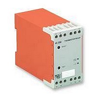
RELAY, THERMISTOR
Manufacturer
BROYCE CONTROL
Datasheet
1.45.200-230.pdf
(1 pages)
Specifications of 45.200-230
Operating Temperature Max
60°C
Operating Temperature Min
-20°C
Output Voltage Max
250VAC
Output Voltage Min
25VDC
Approval Bodies
CE, CSA, C-tick, CUL, IEC, UL
External Length / Height
99mm
Mounting Type
DIN
45200
§
§
§
§
§
§
§
-
- Connect the unit as shown in the diagram above.
- Apply power (green LED on, red LED on, contacts 15
Troubleshooting
- Check wiring and voltage present.
- Check polarity (24V DC).
i
monitored and supply input.
§ TECHNICAL SPECIFICATION
Supply voltage Un:
(AC: 48 - 63Hz)
Supply variation:
Isolation:
Power consumption:
Release value:
Reset Value:
Short circuit detection:
Response time:
Reset time:
Ambient temperature:
Relative humidity:
Contact rating:
Electrical life:
Housing:
Weight:
Mounting option:
Terminal conductor
Approvals:
size:
I
BEFORE INSTALLATION, ISOLATE THE SUPPLY
and 18 closed).
NSTALLATION AND SETTING
use of such information shall be entirely at the user's own risk
The 24V DC* units are not isolated between
accurate (subject to change without prior notice); however,
The information provided in this literature is believed to be
THERMISTOR OVERTEMPERATURE
THERMISTOR SHORT CIRCUIT
THERMISTOR OPEN CIRCUIT
LATCHING FACILITY - SELECTABLE
TEST FACILITY
MONITORS UPTO 6 THERMISTORS
H+44 (0) 1902 773746 G+44 (0) 1902 420639 Email: sales@broycecontrol.com Web: http://www.broycecontrol.com
Installation work must be carried
out by qualified personnel.
TIMING DIAGRAM
DIAGRAMME DES TEMPS
ZEITDIAGRAMM
3100R
1650R
24V, 110V, 230V AC
(Galvanic isolated by transformer)
24V DC*
0.85 - 1.15 x Un
Overvoltage cat. III (IEC 60664)
< 3VA
3100
1650
-20 to +60 C
+95%
1 x C.O.
AC1 250V AC 10A (2500VA)
AC15 250V AC 6A
DC1 25V DC 10A (250W)
to UL94 VO
to BS5584:1978
(EN50 002, DIN 46277-3)
Conforms to: UL, CUL, CSA,
IEC. CE and
10R
0R
10
50mS
350mS
150,000 (AC1)
234g
2 x 1.5mm
2 x 2.5mm
Broyce Control Ltd., Pool Street, Wolverhampton, West Midlands WV2 4HN. England
NON-LATCHING MODE
Thermistor Relay
Relais Thermistor
Thermistor Relais
(to DIN 44081)
2
2
stranded
solid
Compliant
3100R
1650R
10R
0R
LATCHING MODE - Y1 and M linked
§
§
§
§
§
§
§ MONTAGE ET MISE AU POINT
-
- Branchement comme indiqué dans le diagramme ci-
- Appliquer la puissance (LED verte allumée, LED rouge
Intervention (pour régler un problème)
- Vérifier les fils et le voltage présent.
- Vérifier la polarisation (24V DC).
i
controlée et l'alimentation.
§ FICHES TECHNIQUES
Tension d ' alimentation
Variation d ' alimentation: 0.85 - 1.15 x Un
Isolement:
Puissance consommée:
Valeur de déclanchement: 3100
Détection de court-circuit: 10
Temps de résponse:
Temps de remise à zéro:
Température ambiante:
Humidité relative:
Evaluation du contact:
Durée de vie électrique:
Boitier:
Poids:
Option de montage:
Taille du conducteur
Homologations:
Un: (AC: 48 - 63Hz)
terminal:
réserve de changement sans avis préalable) toutefois aux risques et
AVANT MONTAGE, ISOLER L ' ALIMENTATION
dessus.
allumée, contacts 15 et 18 fermés).
Les indications contenues dans ce document sont exactes (sous
Unités à 24V DC* ne sont pas isolées entre l'entree
THERMISTOR SUR-TEMPÉRATURE
THERMISTOR COURT-CIRCUIT
THERMISTOR CIRCUIT OUVERT
POSSIBILITÉ DE FERMETURE
SÉLECTIONNABLE
POSSIBILITÉ DE TESTS
CONTRÔLE JUSQU ' À 6 THERMISTORS
menés à bien par le personnel qualifié.
Des travaux d'installation doivent être
reset pressed
périls de l ' utilisateur
24V, 110V, 230V AC
(Protection galvanisée côté
transformateur)
24V DC*
Overvoltage cat. III (IEC 60664)
< 3VA
1650
-20 à +60 C
+95%
1 x Inverseur
AC1 250V AC 10A (2500VA)
AC15 250V AC 6A
DC1 25V DC 10A (250W)
à UL94 VO
à BS5584:1978
(EN50 002, DIN 46277-3)
Se conformer à UL, CUL, CSA,
IEC. CE et
50mS
350mS
150,000 (AC1)
234g
2 x 1.5mm
2 x 2.5mm
CONNECTION DIAGRAM
DIAGRAMME DE CONNECTION
SCHALTBILDANSCHLUSS
(à DIN 44081)
~
~
2
2
+ve
-ve
multi-filaire
toron
Déférence
Supply
Voltage
(n/c contact)
LATCH
across Y1 and M should
Wiring to latch switch
be short as possible
A1 15
16 18
Y1 M A2
45200
T1 T2
Thermistor to DIN 44081
§
§
§
§
§
§
§ EINBAU UND EINSTELLUNG
-
- Stromversorgung anschliessen wie im Schaltbild unten
- Energie anbringen (LED grün an, LED rot an, Kontakte
Störungsbehebung
- Überprüfung von Leitungen und gegenwärtiger
Spannung.
- Überprüfung von Polung (nur fü
Gleichstromversorgung) (24V DC).
i
der Energiezufuhr nicht isoliert.
§ TECHNISCHE DATEN
Versorgungsspannung
Wechselversorgung:
Isolation:
Energieverbrauch:
Ausrückwerte
Strom-schaltkreisdetektor: 10
Ansprechzeit:
Stellzeit:
Umgebungstemperatur:
Allgemeiner
Kontakt Belastung:
Elektrische Lebensdauer:
Gehäuse:
Gewicht:
Befestigungswahl:
Anschlussklemme
Genehmigungen:
Un: (AC: 48 - 63Hz)
Feuchtigkeitsgehalt:
/ Kabelgrösse:
VOR EINBAU DIE STROMVERSORGUNG
ISOLIEREN
angezeigt.
15 und 18 geschlossen).
Angaben, (Änderungen vorbehalten) jedoch diese Änderungen
load
Es handelt sich in diesen Unterlagen um uns genau bekannte
24V DC* Anlagen sind zwischen den Monitoren und
THERMISTOR ÜBERTEMPERATUR
THERMISTOR OFFANER STROMKREIS
SPERRVORRICHTUNG - SELEKTIV
PRÜFEINRICHTUNG
MONITORE BIS
THERMISTOR KURZSCHLUSS
Installation Arbeit muß von qualifiziertem
laufen auf eigene Gefahr des Benutzers.
Personal durchgeführt werden.
Width / largeur / Breite. 45 mm
MOUNTING DETAILS
INSTRUCTIONS DE MONTAGE
MONTAGEAUFÜHRUNGEN
Insert screwdriver
to release clip
24V, 110V, 230V AC
(galvanische Isolierung bei
Transformator)
24V DC*
0.85 - 1.15 x Un
Overvoltage cat. III (IEC 60664)
< 3VA
3100
1650
-20 bis +60 C
+95%
1 x Wechsler
AC1 250V AC 10A (2500VA)
AC15 250V AC 6A
DC1 25V DC 10A (250W)
bis UL94 VO
bis BS5584:1978
(EN50 002, DIN 46277-3)
Anmerkung: UL, CUL, CSA,
IEC. CE und
Übereinstimmung
50mS
350mS
234g
150,000 (AC1)
2 x 1.5mm
2 x 2.5mm
(bis DIN 44081)
2
2
Litze
Festdraht
78
74
45200-1-B
99
Related parts for 45.200-230
Image
Part Number
Description
Manufacturer
Datasheet
Request
R

Part Number:
Description:
RELAY, CONDUCTIVE LEVEL CONTROL
Manufacturer:
BROYCE CONTROL
Datasheet:
Part Number:
Description:
RELAY, CONDUCTIVE LEVEL CONTROL, 230VAC
Manufacturer:
BROYCE CONTROL
Datasheet:

Part Number:
Description:
TEMPERATURE CONTROLLER, PT100
Manufacturer:
BROYCE CONTROL
Datasheet:

Part Number:
Description:
RELAY, UNDER/OVER CURRENT
Manufacturer:
BROYCE CONTROL
Datasheet:

Part Number:
Description:
RELAY, MULTIFUNCTION, CURRENT
Manufacturer:
BROYCE CONTROL
Datasheet:
Part Number:
Description:
RELAY, 3PHASE ASYMMETRY, 400VAC
Manufacturer:
BROYCE CONTROL
Datasheet:
Part Number:
Description:
RELAY,EARTH LEAKAGE VARIABLE
Manufacturer:
BROYCE CONTROL
Datasheet:
Part Number:
Description:
RELAY,EARTH LEAKAGE VARIABLE PANEL
Manufacturer:
BROYCE CONTROL
Datasheet:

Part Number:
Description:
RELAY, SEQUENCE/LOSS
Manufacturer:
BROYCE CONTROL
Datasheet:

Part Number:
Description:
RELAY, PHASE SEQUENCE FAILURE
Manufacturer:
BROYCE CONTROL
Datasheet:
Part Number:
Description:
RELAY,SEQUENCE/LOSS, 3PHASE
Manufacturer:
BROYCE CONTROL
Datasheet:

Part Number:
Description:
INDICATOR, 3 PHASE
Manufacturer:
BROYCE CONTROL
Datasheet:

Part Number:
Description:
RELAY, SEQUENCE/LOSS, 3PHASE
Manufacturer:
BROYCE CONTROL
Datasheet:

Part Number:
Description:
RELAY, SEQUENCE/LOSS, 3PHASE
Manufacturer:
BROYCE CONTROL
Datasheet:

Part Number:
Description:
RELAY, LOSS/UNDER/OVER VOLT, 3PHASE
Manufacturer:
BROYCE CONTROL
Datasheet: