QO112M100 SQUARE D, QO112M100 Datasheet - Page 19
QO112M100
Manufacturer Part Number
QO112M100
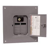
Description
CIRCUIT BREAKER, LOAD CENTER, 240V, 100A
Manufacturer
SQUARE D
Series
QOr
Datasheet
1.QO112M100.pdf
(56 pages)
Specifications of QO112M100
Supply Voltage
240VAC
Current Rating
100A
No. Of Branch Circuits
12
External Depth
3.75"
External Height
17.92"
External Width
14.25"
Enclosure Material
Steel
Lead Free Status / RoHS Status
Contains lead / RoHS non-compliant


03/2007
Slot / Robertson screw
Cross Section of Size 1 Ground Bar
0.3125
[8]
Dimensions:
0.437
[11]
[mm]
in.
TECHNICAL INFORMATION
Grounding Bar Kits
All PK equipment grounding kits are supplied with mounting screws,
necessary installation instructions, and an Equipment Grounding Terminal
self-adhesive label.
1
2
3
4
5
6
7
8
PK0GTA2
PK0GTA6
PK3GTA1
PK4GTA
PK5GTA
PK7GTA
PK9GTA1
PK9GTA
PK12GTA
PK15GTA
PK15GTAL
PK15GTA6
PK18GTA
PK18GTAL
PK23GTA
PK23GTAL
PK27GTA
Number
Catalog
Size
Mounting screw 40205-065-01 (one required).
Mounting screw 21922-18360 (two required).
Mounting screw 21594-14220 (two required).
Mounting screw 21594-14241 (two required).
Mounting screw 21594-14302 (two required).
Mounting screws 21594-14241(two required) and 21594-17121(two required).
3.13 in. (80 mm) on small terminals; 5.25 in. (133 mm) on large terminals.
PK27GTA includes one main grounding lug that mounts with two terminal screws and requires
three terminals for mounting.
QO
IV
VI
III
II
V
I
3
4
3
3
®
1
2
3
3
3
3
3
3
3 8
5
6
5
5
and Homeline
Total
Qty.
27 or
12
15
16
21
18
19
23
24
26
2
6
3
4
5
7
9
9
(1) #14 # 4 or (2) #14 or #12
12
15
15
15
18
18
23
23
27
26
Quantity Each Size
I
3
4
5
7
9
9
See “Wire Range
Cu (AWG)
(1) #14 1 /0
(1) #10 2/0
(1) #1 4/ 0
(1) #6 2/ 0
(1) #6 3/ 0
Table” below.
II III IV V VI
1
1
1
Terminals
1
© 2007 Schneider Electric All Rights Reserved
6
®
Load Centers and Enclosures
6
2
Approximate
1.75
4.61
1.38
1.63
2.25
2.88
3.25
3.78
4.70
5.63
8.13
5.88
6.56
8.81
8.11
9.44
9.36
in.
Overall
Length
Technical Information
mm
117
119
143
207
149
167
224
206
240
238
44
35
41
57
73
83
96
(1) #12 #4 or (2) #12 or #10
One
hole
1.69
One
hole
One
hole
1.25
1.25
One
hole
3.13
3.13
3.13
3.13
3.13
3.13
3.13
3.13
3.13
Mounting
in.
Distance
Between
(1) #14 1/0
Al (AWG)
(1) #1 4/0
(1) #6 2/0
(1) #6 3/0
(1) #6 2 /0
7
Holes
mm
One
hole
One
hole
One
hole
One
hole
43
32
32
80
80
80
80
80
80
80
80
80
7
Mounting
Top or side
Top
Top
Top
Top
Top
Top
Top
Top
Top
Top
Top
Top
Top
Top
Top
Top
19
Related parts for QO112M100
Image
Part Number
Description
Manufacturer
Datasheet
Request
R


Part Number:
Description:
Pushbutton, Non-Illum'd Red "STOP", Momentary, 1NO-1NC, Square 30mm, 10A, 600V
Manufacturer:
SQUARE D
Datasheet:

Part Number:
Description:
KITS,TWIDO? PROGRAMMABLE CONTROLLERS,KITS,TWIDOPACK STARTER KIT - ADVANCED LEVEL,PROGRAMMABLE CONTROLLERS,TWIDO? PROGRAMMABLE CONTROLLERS ,SQUARE D
Manufacturer:
SQUARE D

Part Number:
Description:
LAMPS,INDICATOR,STACKABLE,LAMPS, STACKABLE INDICATOR,VISUAL INDICATING SIGNALS,XVB SERIES INDICATING BANKS ,SQUARE D
Manufacturer:
SQUARE D
Part Number:
Description:
LAMPS,INDICATOR,STACKABLE,LAMPS, STACKABLE INDICATOR,VISUAL INDICATING SIGNALS,XVB SERIES INDICATING BANKS ,SQUARE D
Manufacturer:
SQUARE D
Datasheet:
Part Number:
Description:
I/O EXTENDER MODULE 4 D IN & 2 D OUTPUT
Manufacturer:
SQUARE D
Datasheet:
Part Number:
Description:
CB ACCESSORY, UNDERVOLTAGE TRIP 48V DC
Manufacturer:
SQUARE D
Datasheet: