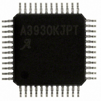
A3930KJPTR-T Allegro Microsystems Inc, A3930KJPTR-T Datasheet - Page 11

A3930KJPTR-T
Manufacturer Part Number
A3930KJPTR-T
Description
IC,Motor Controller,QFP,48PIN
Manufacturer
Allegro Microsystems Inc
Datasheet
1.A3930KJPTR-T.pdf
(21 pages)
Specifications of A3930KJPTR-T
Applications
DC Motor Controller, Brushless (BLDC), 3 Phase
Number Of Outputs
1
Current - Output
500mA
Voltage - Supply
5.5 V ~ 50 V
Operating Temperature
-40°C ~ 150°C
Mounting Type
Surface Mount
Package / Case
48-LFQFP Exposed Pad
Lead Free Status / RoHS Status
Lead free / RoHS Compliant
Voltage - Load
-
Lead Free Status / RoHS Status
Lead free / RoHS Compliant
Other names
620-1289-2
A3930KJPTR-T
A3930KJPTR-T
Available stocks
Company
Part Number
Manufacturer
Quantity
Price
Company:
Part Number:
A3930KJPTR-T
Manufacturer:
ALLEGRO
Quantity:
1 001
Company:
Part Number:
A3930KJPTR-T
Manufacturer:
Allegro MicroSystems, LLC
Quantity:
10 000
Part Number:
A3930KJPTR-T
Manufacturer:
ALLEGRO/雅丽高
Quantity:
20 000
A3930
A3931
In some circumstances, it may be desirable to completely disable
the internal PWM control. This can be done by pulling the RC
pin directly to AGND. This will disable the internal PWM oscil-
lator and ensure that the output of the PWM latch is always high.
Blank Time When the source driver is turned on, a current spike
occurs due to the reverse-recovery currents of the clamp diodes
and switching transients related to distributed capacitance in the
load. To prevent this current spike from erroneously resetting
the source enable latch, the current-control comparator output
is blanked for a short period of time, t
driver is turned on.
The length of t
PWM. It is set by the value of the timing capacitor, CT, according
to the following formulas:
for internal PWM: t
for external PWM: t
A nominal C
external PWM, and 860 ns for internal PWM. The user must
ensure that C
when using the internal sense amplifier.
Diagnostics
Several diagnostic features integrated into the A3930/A3931
provide speed and direction feedback and indications of fault
conditions.
TACHO and DIRO These outputs provide speed and direction
information based on the HE inputs from the motor. As shown in
figure 1, at each commutation point, the TACHO output changes
state independent of motor direction. The DIRO output is updated
at each commutation point to show the motor direction. When
the motor is rotating in the “forward” or positive direction, DIRO
will be high. When rotation is in the “reverse” or negative direc-
tion, DIRO will be low. The actual direction of rotation is deter-
mined from the sequence of the three Hall inputs, Hx. Forward
is when the sequence follows table 2 top-to-bottom and reverse
when the sequence follows table 2 bottom-to-top.
Figure 1. Direction Indication Outputs
Commutation
TACHO
DIRO
Points
T
T
value of 680 pF yields a t
BLANK
is large enough to cover the current spike duration
and
"Forward" Motor Rotation
BLANK
BLANK
is different for internal versus external
(μs) = 1260 × C
(μs) = 2000 × C
BLANK
BLANK
"Reverse" Motor Rotation
T
T
, when the source
(μF), and
(μF) .
of 1.3 μs for
Automotive 3-Phase BLDC Controller
Note that there are some circumstances in which the direction
reported on the DIRO output pin and the direction demanded
on the DIR input pin may not be the same. This may happen if
the motor and load have reasonably high inertia. In this case,
changing the state of the DIR pin will cause the torque to reverse,
braking the motor. During this braking, the direction indicated on
the DIRO output will not change.
ESF The state of the enable stop on fault (ESF) pin will deter-
mine the action taken when a short is detected. For other fault
conditions, the action is defined by the type of fault. The action
taken follows the states shown in table 1.
When ESF = 1, any short fault condition will disable all the
gate drive outputs and coast the motor. This disabled state will
be latched until the next phase commutation or until COAST or
RESET go low.
When ESF = 0, under most conditions, although the fault flags,
FF1 and FF2, are still activated, the A3930/A3931will not disrupt
normal operation and will therefore not protect the motor or the
drive circuit from damage. It is imperative that the master control
circuit or an external circuit take any necessary action when a
fault occurs, to prevent damage to components.
If desired, the active low COAST input can be used as a crude
disable circuit by connecting the fault flags FF1 and FF2 to the
COAST input and a pull-up resistor to V5.
FF1, FF2, and VDSTH Fault conditions are indicated by the
state of two open drain output fault flags, FF1 and FF2, as shown
in table 1. In addition to internal temperature, voltage, and logic
monitoring, the A3930/A3931 monitors the state of the external
MOSFETs and the motor current to determine if short circuit
faults occur or a low load condition exists. In the event that two
or more faults are detected simultaneously, the state of the fault
flags will be determined by a logical AND of the fault states of
each flag.
• Undervoltage VREG supplies the low-side gate driver and the
bootstrap charge current. It is critical to ensure that the voltages
are sufficiently high before enabling any of the outputs. The
undervoltage circuit is active during power-up, and will pull
both fault flags low and coast the motor (all gate drives low)
until V
sufficient to turn on the external power FETs at a battery voltage
as low as 5.5 V, but will not normally provide the rated on-resis-
tance of the FET. This could lead to excessive power dissipation
in the external FET.
REG
is greater than approximately 8 V. Note that this is
and MOSFET Driver
115 Northeast Cutoff
1.508.853.5000; www.allegromicro.com
Allegro MicroSystems, Inc.
Worcester, Massachusetts 01615-0036 U.S.A.
11


